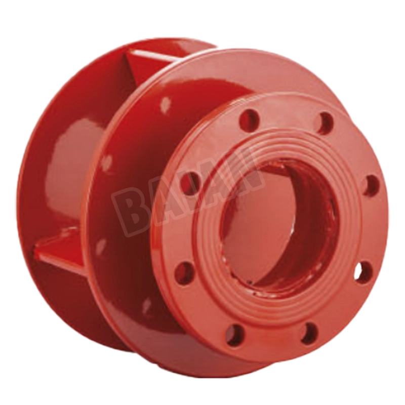
YQFX4-16Q Swirl Preventer
| Product Standards |
| Connection flange pressure level |
PN10/PN16/PN25/150LB/10K/16K |
| Working medium |
Direct drinking water, drinking water, water, sewage, turbid, weak acid or weak alkaline medium |
| Working temperature |
0-120℃ |
| Material |
304 stainless steel, cast steel, cast iron, etc. |
| Flange connection size according to standard |
GB 50974, also meets EU standards |
| BS EN12845 standard design requirements |
| Usage requirements according to standard |
GB/T1724.6, also meets B.S.4504 |
| Meet the requirements |
GB/TT17219 hygiene requirements |
| performance and parameters |
| Working pressure |
PN10/PN16/PN25/150LB/10K/16K |
| Nominal diameter |
DN500-DN600,2''-24'' |
| Working temperature |
0℃-80℃ |
| Applicable medium |
Normal temperature water |
| Manufacturing standard |
GB/JIS/ANSI/BSEN/ISO/DIN |
| Pressure test |
GB/T 13927-2008 |
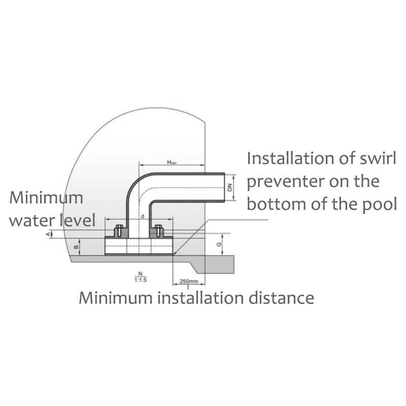
| The dimensions of the swirl preventer comply with the EU standard EN.12845, Article 9.35. |
| Nominal pipe diameter (DN) |
65 |
80 |
100 |
150 |
200 |
250 |
300 |
350 |
400 |
450 |
500 |
| Diameter of swirl preventer top plate d |
230 |
230 |
420 |
620 |
820 |
1020 |
1220 |
1220 |
1220 |
1350 |
1350 |
| Installation position of swirl preventer Hmin |
365 |
365 |
460 |
560 |
660 |
760 |
860 |
860 |
860 |
925 |
925 |
| Minimum immersion depth A |
100 |
100 |
100 |
100 |
100 |
100 |
100 |
100 |
100 |
100 |
100 |
| Minimum distance from suction pipe to pool bottom B |
80 |
80 |
100 |
100 |
150 |
200 |
200 |
300 |
300 |
350 |
350 |
| Minimum allowable water level of water tank C |
180 |
180 |
200 |
200 |
250 |
300 |
300 |
400 |
400 |
450 |
450 |
| The flange connection dimensions comply with the GB/T17241.6 standard |
| Nominal pipe diameter (DN) |
65 |
80 |
100 |
150 |
200 |
250 |
300 |
350 |
400 |
450 |
500 |
| Swirl preventer height G |
PN10 |
94 |
94 |
114 |
116 |
166 |
216 |
216 |
316 |
320 |
370 |
370 |
| PN16 |
94 |
94 |
114 |
116 |
166 |
216 |
216 |
316 |
320 |
370 |
370 |
| PN25 |
94 |
94 |
114 |
120 |
170 |
222 |
222 |
324 |
326 |
376 |
376 |
| E |
PN10 |
185 |
200 |
220 |
285 |
340 |
395 |
445 |
505 |
565 |
615 |
670 |
| PN16 |
185 |
200 |
220 |
285 |
340 |
405 |
460 |
520 |
580 |
640 |
715 |
| PN25 |
185 |
200 |
235 |
300 |
360 |
425 |
485 |
555 |
620 |
670 |
730 |
| F |
PN10 |
145 |
160 |
180 |
240 |
295 |
350 |
400 |
460 |
515 |
565 |
620 |
| PN16 |
145 |
160 |
180 |
240 |
295 |
355 |
410 |
470 |
525 |
585 |
650 |
| PN25 |
145 |
160 |
190 |
250 |
310 |
370 |
430 |
490 |
550 |
600 |
660 |
| MThread size |
PN10 |
M16 |
M16 |
M16 |
M20 |
M20 |
M20 |
M20 |
M20 |
M24 |
M24 |
M24 |
| PN16 |
M16 |
M16 |
M16 |
M20 |
M20 |
M20 |
M20 |
M20 |
M24 |
M24 |
M24 |
| PN25 |
M16 |
M16 |
M20 |
M24 |
M24 |
M27 |
M27 |
M30 |
M33 |
M33 |
M33 |
| Number of threaded holes n |
4 |
PRODUCT DESCRIPTION
1.Swirl preventers are widely used in chemical, energy, water engineering and other fields, especially in fire water pools (boxes),
2.Can ensure that the effective volume is fully utilized and improve the effective utilization rate of fire water pools.
3.Reduce dead water areas and achieve land saving requirements.
4.During rescue, fire water can be used to the maximum extent.
FEATURES
1.Flow optimization: reduce fluid resistance and energy loss.
2.Protect equipment: prevent vibration, wear or measurement errors caused by eddy currents in pumps, flow meters, valves, etc.
3.Versatility: suitable for liquids (water, oil, etc.) and gases (air, steam, etc.).
4.Maintenance-free design: no moving parts, simple structure and long service life.
5.Modular installation: adapt to a variety of pipe sizes (DN15~DN600) and connection methods.
APPLICATION
1.Pump inlet pipeline: prevent pump cavitation and extend pump life.
2.Flow meter upstream: eliminate fluid disturbance and ensure measurement accuracy.
3.Tank outlet/inlet: avoid liquid surface vortex causing gas mixing or incomplete emptying.
4.Cooling/heating system: reduce pipeline vibration and noise.
5.Chemical and energy: maintain stable flow in volatile or high-viscosity medium pipelines.
WORKING PRESSURE
Maximum working pressure 16 bar (230psi).
STANDARD
Product testing is carried out in accordance with GB/T13927 Industrial valve pressure test.
TEMPERATURE RANGE
0 °C to 80°C.
COATING
Fusion Bonded Epoxy Coating.