

Résumé
A pressure reducing valve for water is a self-actuating mechanical device engineered to manage the pressure within a fluid system. Its primary function is to accept a high, often variable, inlet pressure and automatically reduce it to a consistent, lower, and more manageable downstream pressure, irrespective of fluctuations in the upstream supply. The operational principle hinges on an internal dynamic equilibrium between two opposing forces: the downward force exerted by a calibrated compression spring and the upward force of the downstream water pressure acting upon a flexible diaphragm or piston. When downstream pressure falls, the spring force overcomes the water's force, opening the valve to increase flow. Conversely, as downstream pressure rises, it pushes against the diaphragm, compressing the spring and closing the valve to restrict flow. This continuous modulation ensures the protection of downstream components, such as pipes, fittings, and sensitive equipment within residential, commercial, and critical fire protection systems, from the damaging effects of excessive pressure.
Principaux enseignements
- Comprehending how does a pressure reducing valve work water is vital for system protection.
- The valve automatically balances a spring force against downstream water pressure.
- Adjust the top screw to set and maintain your desired outlet water pressure.
- Install a strainer upstream to prevent debris from damaging internal seals.
- Regularly inspect for pressure creep, which indicates a worn or fouled valve seat.
- Proper function is essential for the safety of fire sprinkler and standpipe systems.
Table des matières
- The Foundational Inquiry: Deconstructing the Water Pressure Reducing Valve
- The Mechanical Ballet: An In-Depth Analysis of How a Pressure Reducing Valve Works with Water
- Critical Applications in Fire Protection Systems
- A Pragmatic Guide to Installation, Maintenance, and Troubleshooting
- Frequently Asked Questions (FAQ) About Water Pressure Reducing Valves
- Conclusion
- Références
The Foundational Inquiry: Deconstructing the Water Pressure Reducing Valve
To embark on an exploration of a pressure reducing valve (PRV), also commonly known as a water pressure regulator, one must first grasp its fundamental purpose within the intricate network of a modern water system. At its core, a PRV is an instrument of control, a silent guardian whose sole responsibility is to tame the often unruly force of water pressure. Imagine a municipal water main or a powerful fire pump delivering water at pressures far exceeding what downstream components are designed to handle. This high pressure, if left unchecked, poses a significant threat, capable of causing catastrophic pipe bursts, damaging delicate fixtures, and compromising the integrity of an entire system. The PRV stands as a bulwark against this threat. Its function is not merely to lower pressure, but to do so with a degree of intelligence, delivering a consistent and predictable outlet pressure even when the inlet pressure fluctuates.
This device is a critical component in a vast array of applications, from the plumbing in a residential home to the complex industrial piping of a manufacturing plant. However, its role achieves a heightened level of importance in the context of life-safety systems, particularly fire suppression networks. In these applications, the precise control of water pressure is not a matter of convenience or equipment longevity, but of operational certainty and human safety. Whether in the sprawling metropolises of the Middle East, the industrial hubs of Russia, or the developing urban landscapes of Southeast Asia and South America, the reliability of a fire protection system is non-negotiable, and the PRV is a cornerstone of that reliability.
It is essential to distinguish the function of a pressure reducing valve from that of a pressure relief valve, as the two are often confused yet serve diametrically opposed purposes. A pressure reducing valve is a proactive, normally open device that constantly modulates flow to maintain a set downstream pressure. A pressure relief valve, by contrast, is a reactive, normally closed safety device. It remains inactive until the system pressure exceeds a predetermined safety limit, at which point it opens to vent the excess pressure, preventing system failure. The following table elucidates this critical distinction.
Table 1: Functional Comparison of Pressure Reducing vs. Pressure Relief Valves
| Fonctionnalité | Pressure Reducing Valve (PRV) | Pressure Relief Valve (PRV) |
|---|---|---|
| Primary Function | Proactively controls and maintains a constant lower downstream pressure. | Reactively opens at a high-pressure setpoint to vent excess pressure. |
| Normal State | Normally open (modulating flow). | Normally closed. |
| Operational Principle | Senses downstream pressure to regulate flow. | Senses upstream pressure to release flow. |
| System Placement | Installed in-line to regulate pressure for the entire downstream system. | Installed on a tee or port to protect a vessel or system from over-pressurization. |
| Analogy | A gatekeeper managing traffic flow onto a smaller road. | An emergency exit door that only opens during an unsafe crowd surge. |
Understanding this distinction is the first step in appreciating the nuanced and vital role a pressure reducing valve plays. It is not an emergency device but a continuous regulator, a piece of mechanical intelligence that ensures the entire water system operates within its intended parameters, thereby safeguarding both the infrastructure and the lives that depend on it.
The Mechanical Ballet: An In-Depth Analysis of How a Pressure Reducing Valve Works with Water
To truly comprehend the question, "how does a pressure reducing valve work water?", one must move beyond a surface-level description and venture into the mechanical heart of the device. The operation of a direct-acting PRV is a study in classical mechanics—a beautifully simple yet effective ballet of opposing forces. The valve contains no electronics and requires no external power source; its function is derived entirely from the physical properties of its components and the energy of the water it controls.
The Anatomy of a Direct-Acting Pressure Reducing Valve
A typical direct-acting PRV is composed of a few key components, each with a specific role in the regulatory process. Let us dissect the valve to understand its construction before observing its function.
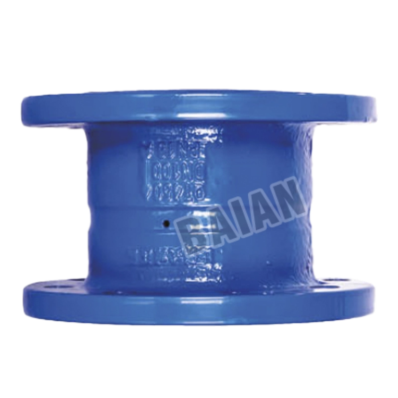
- Valve Body: Typically cast from a robust material like bronze, brass, or stainless steel, the body houses all internal components and features an inlet and an outlet port. An arrow cast into the body indicates the required direction of water flow.
- Spring Chamber: The upper portion of the valve body, which contains the main control spring.
- Adjustment Screw: Located at the very top of the valve, this screw allows for the pre-loading or compression of the spring. Turning it clockwise increases spring compression and raises the set outlet pressure; turning it counter-clockwise decreases compression and lowers the set outlet pressure.
- Spring: This is the heart of the valve's reference force. It is a calibrated compression spring that exerts a constant downward force. The amount of this force is determined by the setting of the adjustment screw.
- Diaphragm or Piston: A flexible, water-impermeable disc (often made of reinforced EPDM or NBR rubber) or a solid piston that separates the spring chamber from the main water passage. The underside of this component is exposed to the downstream water pressure.
- Valve Stem and Poppet (or Seat): The diaphragm is connected via a stem to a poppet or valve plug. This poppet moves up and down, seating against a precisely machined valve seat to restrict or completely stop the flow of water from the high-pressure inlet side to the low-pressure outlet side.
These components work in concert, creating a self-contained feedback loop that continuously senses and adjusts to maintain the desired pressure.
The Dynamic Equilibrium: A Step-by-Step Mechanical Ballet
The operation of the valve can be best understood by examining it in different states of flow. This process is a continuous and fluid series of micro-adjustments, but for the sake of clarity, we can break it down into distinct phases.
-
The Static, No-Flow Condition: Imagine the valve is installed and the main water supply is on, but all downstream fixtures (like sprinklers or faucets) are closed. In this state, the water on the downstream side of the valve is static. This static pressure exerts an upward force on the underside of the diaphragm. The system is designed so that at the desired set pressure, this upward force is slightly greater than the downward force of the spring. This pushes the diaphragm upward, pulling the valve poppet firmly against its seat and completely closing the valve. This prevents the high inlet pressure from "creeping" into the downstream system.
-
Initiation of Flow: Now, a downstream fixture is opened. A sprinkler head activates or a fire hose is opened. Immediately, water begins to flow out of the downstream piping, causing the pressure in that section to drop. This reduction in downstream pressure lessens the upward force on the diaphragm. The downward force of the calibrated spring, which has remained constant, now overcomes the diminished water pressure. The spring pushes the diaphragm down, which in turn pushes the valve poppet away from its seat, opening the valve. High-pressure water from the inlet now flows through the opening into the downstream system.
-
Achieving a State of Dynamic Equilibrium: This is the most critical phase and demonstrates the valve's regulatory genius. As water flows from the high-pressure inlet to the low-pressure outlet, it begins to replenish the pressure that was lost when the fixture was opened. The downstream pressure starts to rise again. This increasing pressure exerts a growing upward force on the diaphragm, opposing the downward push of the spring. The valve does not simply stay wide open. Instead, it finds a new point of equilibrium. The poppet will remain open just enough so that the amount of water entering the downstream system is sufficient to maintain the outlet pressure at the exact level where the upward force of the water on the diaphragm perfectly balances the downward force of the spring. If the flow demand increases (more sprinklers activate), the outlet pressure will momentarily dip, causing the spring to open the valve further to compensate. If the flow demand decreases, the outlet pressure will momentarily rise, causing the water to push the valve slightly more closed. This constant, automatic modulation is how the valve maintains a steady outlet pressure regardless of flow rate (within its operational range).
-
Cessation of Flow: Finally, the last downstream fixture is closed. The flow stops. For a brief moment, water continues to enter through the still-partially-open valve. This causes the downstream pressure to quickly rise. This pressure acts on the diaphragm, and its upward force swiftly overcomes the spring's downward force, pushing the poppet tightly against its seat and sealing the valve. The system returns to the static, no-flow condition, with the downstream side holding steady at the set pressure.
The Role of the Pilot-Operated Pressure Reducing Valve
While direct-acting valves are common and effective, particularly in smaller pipe sizes, they have limitations. In larger diameter pipes (typically above 2-3 inches) and high-flow applications, the forces involved become immense. The diaphragm and spring required to directly control such a flow would need to be enormous, making the valve bulky, slow to react, and expensive.
To solve this, engineers developed the pilot-operated PRV. Think of it as a system of leverage, akin to power steering in a vehicle. A small, highly sensitive direct-acting PRV (the "pilot") is used to control a much larger, more robust main valve.
The mechanism works as follows: a small tube diverts high-pressure water from the inlet to the top of the main valve's diaphragm or piston, holding it closed. The pilot valve is connected to this control chamber. The pilot valve senses the downstream pressure.
- When downstream pressure is at the setpoint, the pilot valve is closed. High pressure remains on top of the main diaphragm, keeping the main valve shut.
- When downstream pressure drops, the pilot valve opens. This vents the pressure from the control chamber on top of the main diaphragm. With the closing pressure gone, the inlet pressure itself pushes the main valve open, allowing a large volume of water to flow.
- As the downstream pressure rises back to the setpoint, the pilot valve begins to close, allowing pressure to build back up in the control chamber and modulating the main valve toward a closed position.
This ingenious two-stage design allows for extremely precise and rapid control of very high flows with a compact and sensitive control mechanism. These are the types of valves most commonly found in the main lines of fire pump systems and municipal water distribution networks.
Critical Applications in Fire Protection Systems
The theoretical understanding of how a pressure reducing valve works water gains profound significance when applied to the domain of fire protection. In these life-safety systems, the failure to control pressure is not an inconvenience; it is a catastrophic failure that can render the entire system useless and endanger lives. The design and application of these valves are strictly governed by standards bodies such as the National Fire Protection Association (NFPA) in the United States, with similar principles adopted globally.
Safeguarding Sprinkler Systems in Varied Structures
Modern architecture, especially in the rapidly growing urban centers of the Middle East, Russia, and Southeast Asia, presents unique challenges for fire protection. High-rise buildings are a primary example. A fire pump at the base of a 40-story building must generate immense pressure to deliver an adequate water supply to the sprinklers on the top floor. This pressure is a combination of the friction loss in the pipes and the static head pressure—the pressure exerted by the sheer weight of the column of water.
A simple calculation reveals the issue: a column of water exerts approximately 0.433 PSI of pressure for every foot of height (or roughly 1 bar for every 10 meters). In a 150-meter-tall building, the static pressure alone on the ground floor is about 15 bar (approx. 217 PSI), even before the fire pump's dynamic pressure is added. This pressure would instantly destroy standard sprinkler heads, pipes, and fittings on the lower floors.
To manage this, buildings are divided into pressure zones. A pressure reducing valve is installed on the main riser at the inlet to each zone. For instance, a valve on the 5th floor might take an inlet pressure of 20 bar and reduce it to a manageable 8 bar for the next ten floors. This ensures that every sprinkler head in the building, from the penthouse to the lobby, operates within its designed pressure range, providing effective and reliable fire suppression.
Controlling Pressure for Standpipe Systems and Fire Hose Connections
Standpipe systems provide the crucial connection points for firefighters to access water within a building. These systems must deliver water to fire hose cabinets at a pressure that is both effective and controllable. NFPA 14, the Standard for the Installation of Standpipe and Hose Systems, sets strict limits on the pressure at a hose connection. If the pressure is too high, a team of firefighters may be unable to safely handle the hose, creating a dangerous situation. If it is too low, the water stream will not have the reach or force needed to combat the fire effectively.
Pressure reducing valves are installed at the hose connections or on the main standpipe line to ensure these pressure requirements are met. They take the high pressure from the riser and deliver a consistent, code-compliant pressure to the hose outlet, allowing firefighters to do their job safely and effectively. This is particularly critical in regions with variable municipal water supplies or in tall buildings where riser pressures are exceptionally high.
Protecting Specialized Fire Suppression Equipment
Modern fire protection extends beyond simple sprinkler systems. Specialized systems, such as foam proportioning systems and deluge systems, rely on delicate and precisely calibrated equipment.
- Foam Systems: Used for flammable liquid fires, these systems mix a foam concentrate with water at a very specific ratio. The proportioning equipment (like eductors or bladder tanks) is designed to operate within a narrow pressure window. Excessive pressure can damage the equipment or, more critically, result in an incorrect foam-to-water ratio, rendering the foam blanket ineffective. A PRV installed upstream of the proportioner guarantees the correct inlet pressure, ensuring the system performs as designed.
- Deluge and Pre-Action Systems: These systems use a deluge valve that is held closed by air or nitrogen pressure in the piping. When a detection system (like a smoke or heat detector) activates, it trips the valve, allowing water to flow to all open sprinklers in the protected area. The tripping mechanism of the deluge valve is sensitive to the incoming water pressure. A PRV ensures this pressure is at the correct level, preventing both failure to operate and damage to the valve itself.
In all these applications, the pressure reducing valve acts as a silent but essential component, translating the raw power of the water supply into the precise, controlled force needed for modern fire suppression technology to function.
Table 2: Application of Pressure Reducing Valves in Fire Protection Systems
| Fire System Component | Location of PRV | Purpose of Pressure Reduction | Typical Set Pressure Range |
|---|---|---|---|
| Sprinkler System Risers | On the main riser at the start of a new pressure zone (e.g., every 10-15 floors). | To protect lower-floor sprinkler heads and piping from excessive static and pump pressure. | 7 – 12 bar (100 – 175 PSI) |
| Standpipe Hose Valves | Directly on the valve outlet or on the branch line feeding the valves. | To provide a safe and manageable hose pressure for firefighters, per NFPA 14. | 4.5 – 7 bar (65 – 100 PSI) for hose use |
| Fire Pump Test Header | On the circulation relief line of the fire pump. | To relieve excess pressure during pump testing when no water is flowing to the system. | Set slightly above pump churn pressure. |
| Foam System Proportioner | Upstream of the foam proportioning device (e.g., eductor, bladder tank). | To ensure the proportioner operates at its designed inlet pressure for accurate foam mixing. | Varies by manufacturer; often 10-14 bar. |
A Pragmatic Guide to Installation, Maintenance, and Troubleshooting
The theoretical elegance of a pressure reducing valve's design is only realized through its proper application and upkeep. The longevity and reliability of these crucial devices depend heavily on correct installation procedures and a consistent maintenance schedule. Neglecting these aspects can lead to premature failure, property damage, and, in the context of a fire protection system, a compromised state of readiness.
Best Practices for Installation
The installation of a PRV is a task that demands precision and adherence to established engineering principles. While specific requirements may vary by manufacturer and local code, several universal best practices apply.
- Correct Orientation: The most fundamental rule is to install the valve in the correct direction of flow. The valve body is almost always marked with a cast-in arrow. Installing the valve backward will prevent it from functioning and may cause damage.
- Strategic Placement: The valve should be installed in an accessible location to allow for future adjustment and maintenance. It is imperative to install shut-off valves both immediately upstream and downstream of the PRV. This allows the valve to be isolated from the system for service without requiring the shutdown of the entire water supply. A bypass line with a globe valve is also highly recommended, especially in critical systems, to allow for manual pressure regulation while the main PRV is being serviced.
- Upstream Filtration: The internal components of a PRV, particularly the valve seat and diaphragm, are sensitive to debris. Grit, scale, or sediment from the water main can become lodged in the valve seat, preventing it from closing properly. This leads to a condition known as "pressure creep," where the downstream pressure slowly rises above the setpoint in a no-flow state. To prevent this, a wye-strainer or other suitable filter should always be installed immediately upstream of the PRV.
- Pressure Gauge Installation: For proper setup and diagnostics, pressure gauges are indispensable. A gauge should be installed on the pipe both upstream and downstream of the valve. This allows for a clear reading of the inlet pressure, verification of the outlet set pressure, and diagnosis of any operational issues.
- Setting the Pressure: The adjustment is done under a no-flow condition. Close a downstream fixture, then turn the adjustment screw on top of the valve. Clockwise rotation increases the set pressure, while counter-clockwise rotation decreases it. Make small adjustments and observe the downstream gauge until the desired pressure is reached.
A Routine for Maintenance
Like any mechanical device, a PRV requires periodic maintenance to ensure it continues to function as designed. For fire protection systems, these maintenance intervals are often mandated by standards like NFPA 25. A typical maintenance routine should include:
- Quarterly Visual Inspection: Check the valve body and connections for any signs of leaks.
- Annual Strainer Cleaning: Isolate the PRV using the shut-off valves. Depressurize the section and remove the cap from the wye-strainer. Clean the mesh screen of any accumulated debris and reinstall it. This is the single most important maintenance task to ensure the valve's longevity.
- Annual Pressure Check: With the system under a no-flow condition, check the downstream pressure gauge. It should match the original set pressure. If it has risen, this indicates pressure creep and requires further investigation. Under a flow condition, verify that the valve is maintaining a stable outlet pressure.
- Exercising the Valve: Periodically, it is good practice to slightly alter the pressure setting and then return it to the original setpoint. This ensures the internal components are not seizing and are moving freely.
- Diaphragm and Seal Inspection (Every 3-5 Years): For critical applications, it is advisable to perform a full service, which involves disassembling the valve and inspecting the diaphragm, O-rings, and valve seat for signs of wear, hardening, or cracking. Most manufacturers offer rebuild kits containing these wearable parts.
Common Troubleshooting Scenarios
When a PRV exhibits faulty behavior, a systematic approach to troubleshooting can quickly identify the root cause.
-
Problem: Low or Fluctuating Outlet Pressure.
- Possible Cause 1: Clogged upstream strainer. This is the most common cause. The strainer is restricting flow to the valve, "starving" it. Solution: Isolate the valve and clean the strainer screen.
- Possible Cause 2: Incorrect pressure setting. The valve may have been adjusted improperly or vibrated out of its setting. Solution: Readjust the pressure using the adjustment screw.
- Possible Cause 3: Undersized valve. The valve may be too small for the flow demand of the system, causing excessive pressure drop even when fully open. Solution: A hydraulic calculation is needed to verify the correct valve size. The valve may need to be replaced with a larger model.
-
Problem: High Outlet Pressure or "Pressure Creep" (Pressure slowly rises in no-flow conditions).
- Possible Cause 1: Debris on the valve seat. A small piece of grit or scale is preventing the valve poppet from sealing completely. Solution: Attempt to flush the valve by briefly opening a downstream fixture fully and then closing it. The high velocity may dislodge the debris. If this fails, the valve must be isolated and disassembled for cleaning.
- Possible Cause 2: Worn valve seat or poppet seal. The soft seal on the poppet or the metal seat itself may be damaged or worn, preventing a tight seal. Solution: The valve must be rebuilt using a manufacturer's repair kit.
- Possible Cause 3: Thermal expansion. In a closed downstream system, water heated by ambient temperature will expand, causing pressure to rise. This is not a valve fault. Solution: An expansion tank may need to be installed on the downstream side.
-
Problem: Valve is Noisy (Chatter or Hammering).
- Possible Cause 1: Oversized valve. If the valve is too large for the typical flow rate, it will operate very close to its seat. The turbulent flow in this near-closed position can cause the poppet to vibrate or "chatter." Solution: The valve may need to be replaced with a smaller, correctly sized model.
- Possible Cause 2: High water velocity. Very high velocities entering the valve can cause turbulence and noise. Solution: Verify that the upstream pipe diameter is adequate.
By following these principles of installation, maintenance, and troubleshooting, the pressure reducing valve can be relied upon to perform its critical function for many years, providing silent, automatic protection for the water systems it serves.
Frequently Asked Questions (FAQ) About Water Pressure Reducing Valves
What is the primary difference between a pressure reducing valve and a pressure relief valve?
A pressure reducing valve is a proactive control device that is normally open and constantly modulates to maintain a set downstream pressure. A pressure relief valve is a reactive safety device that is normally closed and only opens to vent excess pressure when the upstream pressure exceeds a safe limit.
How do I adjust the outlet pressure on my water pressure reducing valve?
To adjust the pressure, you will need a pressure gauge on the downstream side of the valve. First, ensure there is no water flowing in the system. Then, locate the adjustment screw or bolt on the top of the valve. Loosen the lock nut, and turn the screw clockwise to increase the outlet pressure or counter-clockwise to decrease it. Make small adjustments and watch the gauge until the desired pressure is reached, then retighten the lock nut.
My water pressure seems to slowly increase overnight when no water is being used. What causes this?
This condition is called "pressure creep." It is almost always caused by a small amount of debris (like sand or pipe scale) getting caught on the valve's seat, which prevents it from sealing completely. This allows the high inlet pressure to slowly leak past the valve and raise the downstream pressure. The first step is to clean the wye-strainer located upstream of the valve. If that doesn't solve it, the valve may need to be disassembled and cleaned or rebuilt.
How often should a pressure reducing valve in a fire sprinkler system be inspected?
According to NFPA 25, the Standard for the Inspection, Testing, and Maintenance of Water-Based Fire Protection Systems, all pressure control valves should be inspected quarterly. A full test, which involves measuring static and residual pressures under flow conditions, should be performed annually.
Can I install a water pressure reducing valve myself?
For residential plumbing, a mechanically inclined homeowner might be able to install a PRV. However, for any commercial, industrial, or fire protection application, installation must be performed by a qualified and licensed professional. Incorrect installation, especially in a fire system, can have severe consequences and may violate local building and fire codes. A professional will ensure the valve is correctly sized, installed, and set according to all applicable standards.
What happens if a pressure reducing valve fails in a fire protection system?
A failure can manifest in two ways. If it fails in the closed position, it will starve the downstream system of water, rendering sprinklers or hose connections in that zone useless. If it fails in the open position, it will subject the downstream components to the full, excessive upstream pressure, which can lead to burst pipes or ruptured sprinkler heads, causing extensive water damage and compromising the system's ability to control a fire. This is why regular inspection and testing are critical.
Conclusion
The pressure reducing valve, though often hidden from view within the mechanical arteries of a building, performs a function of profound importance. Its operation, a simple yet elegant dance of mechanical forces, stands as a testament to the power of fundamental engineering principles. By automatically and tirelessly taming the raw energy of high-pressure water, it provides an invisible shield, protecting the vast network of pipes, fixtures, and critical life-safety equipment that modern society relies upon. In the context of fire protection, its role transcends mere mechanical function; it becomes an enabler of safety, a guarantor of operational readiness. Understanding how a pressure reducing valve work water is not just an academic exercise for engineers but a crucial piece of knowledge for any stakeholder in building safety and management. From the high-rise towers of Moscow to the industrial facilities of South Africa, this unassuming device ensures that when called upon, our most critical systems will perform as designed, safeguarding property and, most importantly, preserving human life.
Références
Kleiber, M. (2016). Process engineering: Addressing the gap between study and chemical industry. De Gruyter.
Fire Apparatus Manufacturers' Association. (2018). Fire apparatus foam and water additive proportioning systems. FAMA.
Peerless Pump Company. (2020). Fire pumps.
TERAL. (n.d.). Fire fighting pumps.
Fire Rover. (2025). What is a fire suppression system and how does it work?https://firerover.com/what-is-a-fire-suppression-system/
Nanfang Pump Industry Co., Ltd. (n.d.). Firefighting.