


Abstract
A pressure reducing valve is an autonomous hydraulic regulator that converts high, often fluctuating, inlet pressure from a water source into a lower, stable downstream pressure, irrespective of variations in upstream pressure or flow demand. In the context of fire protection engineering, its function is paramount. Unregulated high pressure can compromise system integrity, leading to catastrophic failures such as burst pipes, damaged sprinkler heads, and ineffective water delivery. This can render a fire suppression system useless during an emergency. The valve operates on a principle of equilibrium, using a spring-loaded diaphragm or piston to sense downstream pressure and modulate the valve opening to maintain a predetermined set point. By ensuring that components like sprinklers, hoses, and standpipes operate within their designed pressure ranges, the pressure reducing valve guarantees optimal performance, enhances system longevity, and safeguards both property and the lives of responding firefighters. Its application is indispensable in high-rise buildings, systems with powerful fire pumps, and areas with high municipal water pressure.
Key Takeaways
- A pressure reducing valve automatically lowers high inlet water pressure to a safe, constant outlet level.
- It protects fire sprinkler heads and pipes from damage caused by excessive pressure surges.
- Proper pressure ensures optimal water droplet size and spray patterns for effective fire suppression.
- Select a pressure reducing valve based on flow rate, system demand, and required pressure drop.
- Regular testing and maintenance are necessary for ensuring the valve's reliability during an emergency.
- They are vital in high-rise buildings and systems connected to powerful fire pumps or variable municipal supplies.
Table of Contents
- The Fundamental Role of Pressure in Fire Protection
- Deconstructing the Pressure Reducing Valve (PRV)
- Types of Pressure Reducing Valves in Fire Safety
- The Critical Function of PRVs in Fire Sprinkler Systems
- Integrating PRVs with Other Fire Protection Components
- Selecting the Right Pressure Reducing Valve: A Strategic Approach
- Installation and Maintenance: Ensuring Long-Term Reliability
- Addressing Regional Challenges with Advanced PRV Solutions
- The Future of Pressure Regulation in Fire Protection
- Frequently Asked Questions (FAQ)
- Conclusion
- References
The Fundamental Role of Pressure in Fire Protection
The effective containment and suppression of a fire depend on a delicate balance of factors, but few are as foundational as the management of water pressure within a suppression system. To grasp the significance of a device like a pressure reducing valve, one must first appreciate the dual nature of pressure itself. It is both a necessary force and a potential agent of destruction. Without sufficient pressure, water cannot travel the distance through complex piping networks or exit sprinkler heads with the velocity needed to cover a fire. Yet, with too much pressure, the very system designed to protect a structure can become a source of catastrophic failure.
Why Uncontrolled Pressure is a System's Worst Enemy
Imagine a fire protection system as a vascular network designed to deliver a life-saving agent—water. The municipal supply, or more often a dedicated fire pump, acts as the heart, pushing water into the arteries of the system. In many scenarios, particularly in high-rise buildings where water must be forced dozens of stories high, or in large industrial complexes fed by powerful pumps, this initial pressure is immense. It has to be, simply to overcome gravity and friction loss over long distances.
The problem arises when this high pressure reaches the final delivery points. Sprinkler heads, gaskets, flexible hoses, and pipe joints are all manufactured to withstand a specific maximum operating pressure. Exceeding this limit is not a matter of 'if' but 'when' a failure will occur. A pressure surge could blow a gasket, crack a pipe fitting, or even damage the internal mechanism of a sprinkler head, causing it to fail to activate or, conversely, to discharge improperly. The result is water damage in a non-fire event or, far worse, a system failure during a real fire. This is the danger that a pressure reducing valve is designed to neutralize.
A Simple Analogy: The Garden Hose Principle
To simplify this concept, think about a common garden hose with an adjustable spray nozzle. When the spigot at the house is opened fully, the pressure at the nozzle can be quite high. If you set the nozzle to a fine mist, the water droplets are small and disperse widely, which might be perfect for watering delicate seedlings. If you adjust it to a powerful jet stream, the water travels farther and hits with greater force, ideal for washing a car.
The nozzle, in this analogy, is manually altering the output. A pressure reducing valve performs a similar function automatically for an entire section of a fire protection system. It takes the "full blast" from the spigot (the high-inlet pressure from the pump or city main) and, without any human intervention, ensures the water exiting into the downstream pipes is at a consistent, "just right" pressure. It guarantees that whether one sprinkler head activates or twenty, the pressure delivered to them remains stable and within the safe, effective range prescribed by fire safety engineers. Without it, the system would be trying to water delicate seedlings with a power-washing jet, destroying them in the process.
Deconstructing the Pressure Reducing Valve (PRV)
At its heart, a pressure reducing valve is a marvel of mechanical autonomy. It is a self-contained, self-regulating device that stands guard over a system, sensing and responding to fluid dynamics without the need for external power or human command. Understanding its internal mechanics reveals a simple yet elegant application of physics to solve a complex engineering problem.
What is a Pressure Reducing Valve at its Core?
A pressure reducing valve, often abbreviated as PRV, is a type of control valve designed to take a high and potentially variable pressure at its inlet and deliver a lower, constant pressure at its outlet. This function remains consistent even when the inlet pressure fluctuates or the demand for water (flow rate) downstream changes. It is not a flow control valve; its primary objective is pressure management. It works by introducing a variable restriction in the water's path. As downstream pressure changes, the valve automatically adjusts the size of this restriction to maintain the desired outlet pressure. This set outlet pressure is determined during installation and commissioning and is a core parameter of the system's hydraulic design.
The Inner Workings: A Mechanical Balancing Act
The operation of most pressure reducing valves relies on a force-balance principle. Imagine a set of scales. On one side, you have the force of the downstream water pressure pushing up. On the other side, you have a pre-set mechanical force, usually from a calibrated spring, pushing down.
- Sensing: A diaphragm or a piston inside the valve is exposed to the downstream (outlet) pressure. As this pressure increases, it pushes upward on the diaphragm.
- Balancing: An adjustment spring, compressed by an adjusting screw on top of the valve, exerts a downward force. This downward force corresponds to the desired outlet pressure.
- Modulating: The diaphragm is connected to the valve's obturator (the part that opens and closes, like a plug or a disc). When the downstream pressure is at the set point, the upward force from the water and the downward force from the spring are in equilibrium. The valve is open just enough to satisfy the current flow demand.
- Adjusting: If the downstream pressure begins to rise above the set point (perhaps because a sprinkler has closed), the increased upward force overcomes the spring force. This pushes the diaphragm up, causing the valve to move toward the closed position. This increases the restriction, and the pressure drops back to the set point. Conversely, if downstream pressure falls (because more sprinklers have opened), the spring force overcomes the water pressure, pushing the diaphragm down and opening the valve further to allow more flow and bring the pressure back up.
This continuous, automatic modulation is what makes the pressure reducing valve so effective. It is constantly making tiny adjustments to maintain a state of hydraulic equilibrium.
Table 1: Direct-Acting vs. Pilot-Operated PRVs
Two primary designs accomplish this task, each with distinct advantages suited for different applications. Understanding their differences is key to proper valve selection.
| Caraterística | Direct-Acting Pressure Reducing Valve | Pilot-Operated Pressure Reducing Valve |
|---|---|---|
| Operating Principle | A single valve mechanism where the spring acts directly on the main valve plug. | A two-stage system: a small pilot valve controls a larger main valve. |
| Control Accuracy | Good, but can exhibit "droop" (outlet pressure drops slightly as flow increases). | Excellent, provides very precise and stable pressure control across a wide range of flows. |
| Capacity/Size | Typically used for smaller pipe sizes (e.g., up to DN50 or 2 inches) and lower flow rates. | Suitable for large pipe sizes (DN50 to DN600 or more) and very high flow rates. |
| Sensitivity | Less sensitive to very small pressure variations. | Highly sensitive; the pilot can react to minor fluctuations to command the main valve. |
| Complexity | Simple, robust design with fewer parts. Easier to maintain. | More complex, with small internal passageways that can be prone to blockage from debris. |
| Common Application | Point-of-use pressure reduction, small branch lines, or individual appliance protection. | Main lines in fire sprinkler/standpipe systems, municipal water distribution, large industrial plants. |
Types of Pressure Reducing Valves in Fire Safety
While the underlying principle of balancing forces remains constant, the mechanical execution of this principle gives rise to different types of pressure reducing valves. In the world of fire protection, the choice between them is not arbitrary; it is dictated by the specific demands of the system, such as the required flow rate, the degree of precision needed, and the overall system architecture. The two most prominent categories are direct-acting and pilot-operated valves.
Direct-Acting PRVs: Simplicity and Reliability
The direct-acting pressure reducing valve is the most straightforward design. As described in the balancing act analogy, it consists of a closing element (like a globe-style plug), a sensing element (a diaphragm or piston), and a large, calibrated spring. The downstream pressure acts directly on the diaphragm, and its force is opposed by the spring. The position of the plug is a direct result of the equilibrium between these two forces.
Their simplicity is their greatest strength. With fewer moving parts and no complex internal channels, they are inherently robust and less susceptible to failure from dirty water or small debris, which can be a concern in some water supplies. Maintenance is generally simpler and faster. However, this design has a characteristic known as "droop" or "offset." This means that as the flow demand downstream increases significantly, the outlet pressure will tend to drop slightly below the original set point. For many applications, this minor pressure drop is perfectly acceptable. They are an excellent choice for smaller-diameter lines or for protecting specific zones or pieces of equipment where flow rates are predictable and not excessively high.
Pilot-Operated PRVs: Precision for Complex Systems
For large-scale fire protection systems, such as those found in sprawling industrial facilities, airports, or towering skyscrapers in regions like the Middle East, a higher level of precision is required. This is where the pilot-operated pressure reducing valve excels.
A pilot-operated PRV is essentially a system of two valves in one body: a small, highly sensitive pilot valve and a much larger main valve. The main valve, which handles the high flow, is typically a diaphragm-actuated globe or angle valve that is designed to be opened by the inlet pressure itself. However, it can only open if pressure is released from its control chamber. This is the job of the pilot valve.
The small pilot valve senses the downstream pressure, just like a direct-acting valve does. Instead of directly moving the large main plug, it meters a tiny amount of flow from the main valve's control chamber.
- If downstream pressure is too low, the pilot opens, releasing pressure from the top of the main valve's diaphragm. This creates a pressure differential that allows the high inlet pressure to easily push the main valve open, restoring downstream pressure.
- If downstream pressure is too high, the pilot closes, allowing inlet pressure to build up in the control chamber, which pushes the main valve toward the closed position.
Because the pilot is only controlling a very small flow, it can be made extremely sensitive and precise. This two-stage action allows the valve to maintain a very stable outlet pressure across a huge range of flow rates, from a mere trickle to a full-system discharge. This precision is why pilot-operated valves are the standard for main-line pressure control in demanding fire protection applications. You can find a variety of these high-quality fire protection pressure reducing valves that are specifically designed to meet these rigorous demands.
Table 2: Application-Based PRV Selection
The decision on which valve to use is a practical one based on system requirements. The following table provides a general guide for fire protection applications.
| Application Scenario | Recommended Valve Type | Rationale |
|---|---|---|
| High-Rise Standpipe System | Pilot-Operated | Requires precise pressure control at each floor landing to ensure safe and effective pressure for firefighter hose lines, regardless of how many lines are in use. |
| Sprinkler System Main Line | Pilot-Operated | Needs to handle a wide range of flows, from a single activating sprinkler to a full zone discharge, while maintaining stable pressure for optimal sprinkler performance. |
| Fire Hose Cabinet/Station | Direct-Acting | Protects a single hose or a small group of them. Flow rates are relatively predictable, and the simplicity of a direct-acting valve offers high reliability. |
| Test and Drain Line | Direct-Acting | Used to reduce pressure for testing purposes where extreme precision is not the primary concern. Its robustness is an advantage. |
| Deluge System Manifold | Pilot-Operated | Deluge systems involve very high flow rates when activated. A pilot-operated valve is necessary to handle the large volume and maintain the correct downstream pressure. |
| Fire Pump Discharge | Pilot-Operated | Placed immediately after a powerful fire pump to step down the very high pump head pressure to a usable system pressure. Must handle high flows and high differential pressure. |
The Critical Function of PRVs in Fire Sprinkler Systems
Nowhere is the role of a pressure reducing valve more clearly illustrated than in an automatic fire sprinkler system. These systems are the first line of defense in most commercial, industrial, and residential buildings. Their effectiveness is directly tied to the hydraulic principles governing water delivery, and pressure is the master variable in that equation. A pressure reducing valve acts as the silent guardian ensuring the entire system operates not just as designed, but optimally.
Preventing Over-Pressurization and Component Failure
The most immediate function of a pressure reducing valve in a sprinkler system is structural protection. A typical commercial sprinkler head is rated for a maximum working pressure, often around 175 psi (12 bar). However, the fire pumps needed to serve a multi-story building can easily generate pressures far exceeding 300 psi (20.7 bar). Connecting these sprinklers directly to such a high-pressure source would be an invitation for disaster (National Fire Protection Association, 2022).
The PRV is installed to create pressure zones. For example, in a 30-story building, a pump at the base might generate enough pressure to serve the top floors. A pressure reducing valve installed on the supply lines for the 5th floor would take that high pressure and step it down to a safe and effective level, perhaps 120 psi (8.3 bar), for all the sprinklers on that floor. Another PRV on the 15th floor would do the same. This zoning strategy ensures that no component in the system is ever subjected to pressures beyond its design limits, preventing leaks, bursts, and catastrophic failure.
Ensuring Correct Droplet Size and Spray Pattern
The effectiveness of a fire sprinkler is not just about discharging water; it is about discharging it in the most effective way to control or extinguish a fire. The design of a sprinkler head's deflector—the small, grooved plate that the water strikes—is carefully engineered to produce a specific spray pattern and a specific range of water droplet sizes at a given pressure.
- If pressure is too low: The water will not have enough energy to form the correct pattern. It may fall in a weak, concentrated stream directly below the sprinkler, leaving large areas of the room unprotected. The droplets will be too large and may not absorb enough heat from the fire plume.
- If pressure is too high: The water smashes against the deflector with excessive force. This can create a fine, fog-like mist instead of the intended droplets. While this might seem good for heat absorption, these tiny droplets can be easily carried away by the hot gases rising from the fire and may never even reach the burning fuel source on the floor. The spray pattern can also be distorted, again leaving gaps in coverage.
A pressure reducing valve ensures that the pressure at the sprinkler head is within the sweet spot defined by the manufacturer and fire codes, typically between 7 psi (0.5 bar) and 175 psi (12 bar), depending on the specific application (Hall & Mckenna, 2018). This guarantees that the sprinkler produces the exact pattern and droplet size for which it was designed, maximizing its ability to control the fire.
Case Study: High-Rise Fire Safety in Dubai
Consider the challenge of protecting a super-tall building, a common sight in cities like Dubai. A fire pump at ground level must generate enormous pressure to lift water over 500 meters. The static pressure from the column of water alone is immense. Without pressure regulation, the sprinklers on the lower floors would be exposed to pressures several times their rated capacity.
In such a building, a sophisticated, multi-zoned system is employed. A large, pilot-operated pressure reducing valve might be installed on the main riser every 10 to 15 floors. Each valve creates a manageable pressure zone for that section of the building. This not only protects the sprinklers but also ensures that if firefighters connect hoses to the standpipe outlets on a lower floor, they are not met with a dangerously uncontrollable blast of water. The strategic placement of PRVs is a non-negotiable element of the fire safety design for such structures, making them habitable and safe.
Integrating PRVs with Other Fire Protection Components
A fire protection system is an ecosystem of interconnected parts. A pressure reducing valve does not operate in isolation. Its function is intimately linked to the performance of other key components, including fire pumps, standpipes, and various other types of valves. Understanding these relationships is fundamental to designing a cohesive and reliable system. The PRV often acts as the mediator, harmonizing the powerful output of one component with the sensitive operating requirements of another.
PRVs in Standpipe Systems: Protecting Firefighters
Standpipe systems are the vertical arteries that allow firefighters to access water on any floor of a building. They consist of a network of pipes and hose connections. When firefighters arrive, they connect their hoses to these outlets. The pressure at these outlets is a matter of life and death.
If the pressure is too low, their hose stream won't reach the fire. If the pressure is too high, the hose becomes a dangerous, uncontrollable weapon. The force, known as nozzle reaction, can be so great that it can throw a firefighter off balance or make the hose impossible to handle, wasting precious time and water. The National Fire Protection Association (NFPA) 14, the standard for standpipe systems, sets strict limits on the pressure at these outlets (National Fire Protection Association, 2023).
A pressure reducing valve, often a specialized type listed for standpipe service, is installed just before the hose connection. Its job is to guarantee that no matter what the pressure is in the main standpipe riser, the pressure delivered to the firefighter's hose is within the safe, usable range—typically capped at 175 psi (12 bar) for a 2.5-inch connection. This ensures that firefighters have a reliable and predictable tool to work with, allowing them to focus on fighting the fire.
The Relationship with Fire Pumps and Deluge Systems
Fire pumps are the workhorses of many suppression systems, especially in large buildings or facilities without adequate municipal water pressure. These pumps are designed to deliver a high volume of water at a very high pressure. A pressure reducing valve is often the pump's essential partner. It is placed downstream of the pump to "step down" the pressure to what the system requires. For instance, a pump might discharge at 250 psi (17.2 bar), but the sprinkler system is designed for 160 psi (11 bar). The PRV bridges this gap.
In deluge systems, which are used to protect high-hazard areas like aircraft hangars or chemical plants, a large volume of water is released simultaneously through all open sprinklers in a zone. A pilot-operated pressure reducing valve is often used at the main deluge valve riser. When the system activates, the PRV must respond instantly to the massive flow demand, ensuring the deluge of water is delivered at the correct pressure to be effective without damaging the open-nozzle system. It modulates the intense output of the fire pump to the precise needs of the deluge zone.
Coordination with Butterfly and Check Valves
Other valves play supporting roles. Butterfly valves, as noted by industry resources like , are primarily used as shut-off or isolation valves. A butterfly valve might be installed upstream and downstream of a pressure reducing valve. This allows maintenance personnel to isolate the PRV from system pressure to safely perform inspections, repairs, or replacement without draining the entire system.
Check valves, also known as non-return valves, are also crucial. They ensure water flows in only one direction. A check valve is often placed after a PRV to prevent any potential backpressure from the downstream side from affecting the valve's delicate diaphragm or pilot mechanism. This coordination ensures each valve performs its specific function without interfering with the others, creating a stable and predictable hydraulic circuit.
Selecting the Right Pressure Reducing Valve: A Strategic Approach
Choosing the correct pressure reducing valve is a critical engineering decision that profoundly impacts the safety and reliability of a fire protection system. It is not a one-size-fits-all component. The selection process involves a careful analysis of the hydraulic conditions of the system, the specific application, and the governing safety standards. A mistake in selection can lead to poor performance, premature failure, or even a complete inability of the valve to control pressure under fire conditions.
Key Parameters: Flow Rate, Inlet Pressure, and Desired Outlet Pressure
The selection process begins with three fundamental pieces of data:
- Maximum and Minimum Flow Rate (Q): The valve must be sized to handle the entire range of expected water flow. This could be the low flow of a single sprinkler activating or the massive flow of an entire zone or standpipe system. Sizing a valve too large for the typical flow (a common mistake) can cause "hunting," where the valve constantly opens and closes, leading to instability and wear. Sizing it too small will "starve" the system, preventing it from delivering the required water.
- Inlet Pressure Range (P1): The valve must be able to withstand the maximum possible pressure from the source, including any potential surges from the municipal supply or a fire pump turning on. It also needs to function correctly at the minimum expected inlet pressure.
- Desired Outlet Pressure (P2): This is the target pressure for the downstream system, determined by the fire protection engineer's hydraulic calculations. The valve chosen must be capable of maintaining this set pressure accurately across the full range of flow rates.
The pressure drop across the valve (the difference between P1 and P2) is also a key factor. A valve must be chosen that can handle the required pressure reduction without causing excessive noise, vibration, or cavitation (the formation and collapse of vapor bubbles, which can be highly destructive).
Understanding System Demand: Static vs. Residual Pressure
A nuanced understanding of pressure types is necessary for correct PRV application.
- Static Pressure: This is the pressure in the system when no water is flowing. It is the potential energy in the system. A PRV must be able to hold the set outlet pressure under static (no-flow) conditions without leaking or "creeping" up.
- Residual Pressure: This is the pressure that remains in the system when water is flowing. It is the pressure available to do work, such as pushing water out of a sprinkler. A PRV is selected to maintain a specific residual pressure at a given flow rate.
Fire protection design involves calculating the required residual pressure at the most remote sprinkler head to ensure it gets enough water. The PRV's performance is central to this calculation. The engineer must account for the pressure loss through the PRV itself, along with friction losses in the pipes, to ensure the final pressure at the sprinkler is adequate.
Navigating International Standards: NFPA and API
Compliance with recognized standards is not optional; it is a requirement for life safety systems. The most prominent standard in fire protection is from the National Fire Protection Association (NFPA) in the United States, whose codes are widely adopted internationally.
- NFPA 13 (Standard for the Installation of Sprinkler Systems): This standard provides detailed rules on where and when pressure reducing valves must be used, how they should be installed (e.g., with pressure gauges on the inlet and outlet), and how they must be tested (National Fire Protection Association, 2022).
- NFPA 14 (Standard for the Installation of Standpipe and Hose Systems): This provides specific requirements for PRVs used on firefighter hose connections, focusing on limiting the outlet pressure to safe, manageable levels (National Fire protection Association, 2023).
Valves used in these systems must be "listed" and "approved" by a recognized testing laboratory, such as UL (Underwriters Laboratories) or FM (Factory Mutual). This certification ensures the valve has been rigorously tested to perform reliably under fire conditions. For related industries like oil and gas, standards like the API 6FA fire test, as mentioned by sources like , provide a benchmark for how valves must perform when exposed to extreme heat, ensuring they maintain their integrity.
Material Considerations for Diverse Environments
The environment in which the valve will operate plays a significant role in material selection. A valve installed in a dry, climate-controlled building has different needs than one in a corrosive coastal or industrial environment.
- Body Material: Ductile iron is a common and robust choice for fire protection. However, for marine applications or in regions with high humidity and salinity like Southeast Asia, bronze or stainless steel bodies offer superior corrosion resistance, ensuring a longer service life.
- Internal Components (Trim): The internal parts, such as the seat, plug, and stem, are critical. Stainless steel is a standard for its durability and resistance to corrosion and erosion. For particularly aggressive water conditions, more exotic alloys may be specified.
- Elastomers (Diaphragms and Seals): The rubber components must be compatible with the water being used and any potential trace chemicals. EPDM is a common choice for its excellent performance with water and its long life.
By carefully considering these technical parameters, standards, and environmental factors, an engineer can confidently explore a range of pressure regulating solutions and select a valve that will serve as a reliable and effective guardian of the fire protection system for decades.
Installation and Maintenance: Ensuring Long-Term Reliability
The selection of a high-quality pressure reducing valve is only the first step. Its long-term reliability is entirely dependent on proper installation and a disciplined maintenance regimen. A perfectly specified valve installed incorrectly or neglected for years can become a point of failure, providing a false sense of security. In life safety systems, where performance on demand is absolute, installation and maintenance are not afterthoughts; they are integral parts of the component's life cycle.
Best Practices for PRV Installation
Correct installation is foundational to the valve's function. While specific manufacturer instructions should always be followed, several universal best practices apply, many of which are codified in standards like NFPA 13 and 14.
- Orientation: Most PRVs are designed to be installed in a specific orientation, typically in a horizontal pipe with the spring chamber (bonnet) facing up. Installing a valve upside down or vertically when it is not designed for it can interfere with the internal movement of the diaphragm and spring, leading to erratic performance.
- Location and Accessibility: The valve should be installed in a location that is easily and safely accessible for inspection, testing, and maintenance. It should not be hidden behind walls or above inaccessible ceilings.
- Upstream and Downstream Piping: It is recommended to have a straight run of pipe, typically 5-10 pipe diameters long, both upstream and downstream of the valve. This helps to stabilize turbulent flow and allows the valve to sense pressure more accurately.
- Isolation Valves and Bypass: As mentioned earlier, installing isolation valves (like butterfly or ball valves) before and after the PRV is a best practice. This allows the valve to be taken out of service for maintenance without shutting down the entire system. A bypass line, often with a normally closed globe valve, can be installed around the PRV to allow for emergency water flow while the main valve is being serviced.
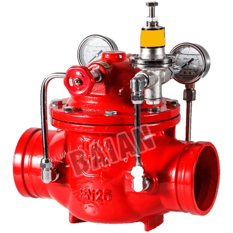
- Pressure Gauges: Calibrated pressure gauges must be installed on both the inlet and outlet sides of the valve. These are not optional accessories; they are essential diagnostic tools that provide an immediate visual confirmation of the valve's performance.
- Strainers: In systems where the water supply may contain sediment, rust, or other debris, installing a strainer immediately upstream of the PRV is highly advisable. This protects the delicate internal pilot mechanisms and seating surfaces from damage or blockage, which is a common cause of failure in pilot-operated valves.
Developing a Routine Inspection and Testing Schedule
A pressure reducing valve is a dynamic mechanical device that must be periodically tested to ensure it will function in an emergency. NFPA 25 (Standard for the Inspection, Testing, and Maintenance of Water-Based Fire Protection Systems) provides a clear framework for this.
- Weekly/Monthly Visual Inspection: A simple walk-by inspection should be conducted to check for leaks, physical damage, or incorrect pressure readings on the gauges (assuming a static system).
- Annual Operational Test: This is a more thorough test. It involves flowing water through the valve and verifying its performance under both static (no-flow) and dynamic (flow) conditions. The test confirms that the valve opens and closes smoothly and maintains the correct downstream pressure at a given flow rate. This is done by opening a test outlet (like an inspector's test connection or a hose valve) and observing the pressure gauges.
- Full Internal Inspection (Every 5 Years): NFPA 25 requires a full internal inspection of the valve every five years. This involves isolating and disassembling the valve to check for wear, damage, or degradation of internal components like the diaphragm, seat, and spring. Worn parts should be replaced using a manufacturer-approved rebuild kit.
Troubleshooting Common PRV Issues
With proper installation and maintenance, PRVs are highly reliable. However, issues can arise. Understanding the common symptoms and their likely causes can expedite troubleshooting.
- Outlet Pressure Too High (Creeping): This often occurs under no-flow conditions. The most common cause is dirt or debris trapped on the valve seat, preventing it from closing tightly. It could also indicate a worn seat or a failed diaphragm.
- Outlet Pressure Too Low: Under flow, this might indicate the valve is undersized for the demand. It could also be caused by a blockage in the valve or an upstream strainer, a broken spring, or an incorrectly adjusted pilot.
- Erratic or Fluctuating Pressure: This "hunting" behavior can be caused by a valve that is oversized for the flow rate. It may also point to trapped air in the spring chamber or issues with the pilot control system.
- Noise or Vibration: Loud noise (chatter) or vibration can be a sign of high-velocity flow or cavitation. This is often a result of a very large pressure drop across the valve and may indicate that the valve was improperly selected for the application.
Regular attention to these installation and maintenance protocols transforms a pressure reducing valve from a passive piece of hardware into an actively managed, reliable component of a building's life safety strategy.
Addressing Regional Challenges with Advanced PRV Solutions
The principles of fire protection are universal, but their application must be adapted to local conditions. The diverse geographies, economies, and building practices found across South America, Russia, Southeast Asia, and the Middle East present unique challenges for water pressure management. A sophisticated understanding of these regional factors is essential for designing robust fire protection systems, and the pressure reducing valve is often a key tool in addressing them.
Managing Variable Municipal Water Supplies in South Africa
In many parts of South Africa and other developing regions, municipal water infrastructure can be inconsistent. Water pressure can fluctuate dramatically throughout the day due to high demand, intermittent pumping schedules, or aging infrastructure. A fire protection system connected directly to such a supply faces a significant challenge. The pressure might be inadequate one moment and dangerously high the next when a municipal booster pump kicks in unexpectedly.
Here, a pressure reducing valve serves a dual purpose. When paired with a storage tank and a dedicated fire pump, it ensures the building's system is isolated from municipal fluctuations. However, even in systems directly fed by the city main, a PRV is vital. It acts as a buffer, taking the variable and unpredictable inlet pressure and delivering a constant, reliable pressure to the sprinkler system. This ensures that regardless of what is happening in the city's pipes, the building's first line of defense remains stable and ready.
High-Pressure Pumping in Russia's Expansive Industrial Zones
Russia's vast territory is home to massive industrial and resource extraction facilities, from sprawling petrochemical plants to remote mining operations. These sites often require immense fire protection systems covering large areas. Fire pumps must be exceptionally powerful to move water over long distances and to high elevations within complex processing structures. The discharge pressures from these pump houses can be extreme.
In these applications, heavy-duty, pilot-operated pressure reducing valves are indispensable. They are often installed in series or in parallel configurations within valve houses to manage the massive flow rates and high-pressure differentials. The material selection is also critical, requiring valves that can withstand not only high pressures but also potentially low temperatures in regions like Siberia. The use of robust ductile iron or specialized steel alloys, along with low-temperature rated elastomers, is common practice to ensure reliability in these harsh environments (Gong, et al., 2021).
Tailoring Systems for Seismic Activity in South American and Southeast Asian Regions
Many countries along South America's Pacific coast and throughout Southeast Asia are located in the "Ring of Fire," an area with high seismic activity. Earthquakes pose a unique threat to rigid piping systems. The violent ground shaking can cause pipes to break, joints to fail, and system integrity to be compromised at the very moment a fire is most likely to break out due to ruptured gas lines or electrical shorts.
While flexible pipe couplings are the primary defense against seismic movement, pressure reducing valves also play a role. By keeping the static pressure in the system at the lowest necessary level rather than the maximum available pressure, the overall stress on pipes and fittings is reduced. In the event of a pipe rupture during an earthquake, a lower-pressure system will have a less violent discharge, potentially reducing the rate of water loss and preserving some system capacity for firefighting efforts. Furthermore, the PRVs themselves must be braced and installed according to seismic codes to ensure they remain operational after a seismic event.
The Future of Pressure Regulation in Fire Protection
The field of fire protection, while rooted in time-tested principles, is not static. Technological advancements are continuously refining the tools and strategies used to safeguard lives and property. The humble pressure reducing valve is also evolving, moving from a purely mechanical device to a smarter, more integrated component of a building's overall safety and management system. The future points toward greater precision, data integration, and sustainability.
Smart Valves and IoT Integration
The next frontier for pressure management is the integration of digital technology. The "smart" pressure reducing valve is emerging as a key innovation. These valves incorporate electronic sensors, actuators, and communication capabilities.
- Remote Monitoring and Control: Instead of relying solely on manual gauge readings during a physical inspection, a smart PRV can continuously transmit its status—inlet pressure, outlet pressure, flow rate, valve position—to a central building management system (BMS) or a dedicated fire alarm control panel. This allows facility managers to monitor the health of their system in real time from anywhere in the world.
- Predictive Maintenance: By analyzing trends in the data, the system can predict potential failures before they happen. For example, if a valve starts to show minor, erratic pressure fluctuations, the system could flag it for inspection, identifying a potential debris issue or a wearing component long before it becomes a critical failure.
- Dynamic Adjustment: In highly sophisticated "performance-based" designs, a smart PRV could even have its set point adjusted remotely. For instance, in a complex industrial process, the required fire protection pressure might change based on the materials being handled. A smart valve could be programmed to adapt to these changing conditions, providing a level of tailored protection that is impossible with a fixed mechanical valve. This Internet of Things (IoT) connectivity transforms the valve from a passive component into an active, data-rich node in the building's safety network (Jeschke, et al., 2017).
Sustainable Materials and Energy-Efficient Designs
There is also a growing focus on the environmental impact and life-cycle cost of building components. Valve manufacturers are responding with innovations in materials and design.
- Lead-Free and Recycled Materials: In response to global health and environmental regulations, there is a strong push toward using lead-free alloys for bronze and brass components. Manufacturers are also exploring the use of recycled metals and more sustainable manufacturing processes to reduce the carbon footprint of their products.
- Energy Efficiency: While a PRV itself does not consume energy directly, it influences the energy consumption of the fire pump. By optimizing pressure management and reducing unnecessary over-pressurization, a well-designed system with efficient PRVs can allow for the use of smaller, more energy-efficient fire pumps. Newer pilot designs are also being developed that consume less water during their regulatory action, contributing to water conservation, which is a significant concern in many regions.
The future of the pressure reducing valve is one of enhanced intelligence, greater efficiency, and deeper integration. It will remain a fundamentally mechanical device at its core, but it will be wrapped in a layer of data and connectivity that will make fire protection systems safer, more reliable, and easier to manage than ever before.
Frequently Asked Questions (FAQ)
What is the main difference between a pressure reducing valve and a pressure relief valve? A pressure reducing valve's job is to maintain a constant downstream (outlet) pressure, regardless of what the higher inlet pressure is. It is normally open and modulates toward the closed position as downstream pressure rises to its set point. A pressure relief valve is a safety device that stays normally closed and only opens when the upstream (inlet) pressure exceeds a safe limit, venting excess pressure to prevent a catastrophic failure. They serve opposite functions.
Can a pressure reducing valve also increase pressure? No, a pressure reducing valve can only lower pressure. It is a passive device that works by creating a restriction. It has no mechanism, like a pump, to add energy to the water and increase its pressure. If the inlet pressure drops below the valve's set outlet pressure, the valve will simply open fully and the outlet pressure will become equal to the inlet pressure (minus a small amount of friction loss).
How do I know what pressure to set my PRV to? The set pressure for a pressure reducing valve in a fire protection system is not arbitrary; it is a critical value determined by a qualified fire protection engineer during the system design phase. It is based on detailed hydraulic calculations that consider the building's height, the type of sprinklers used, pipe sizes, and the requirements of fire safety codes like NFPA 13. You should never adjust the pressure setting without consulting the system's design documents or a certified professional.
Why is my pressure reducing valve making a loud noise? Loud noise, such as chattering, whistling, or hammering, is usually a symptom of a problem. Common causes include: excessively high flow velocity due to a very large pressure drop, cavitation (the formation and collapse of vapor bubbles in high-velocity flow), an oversized valve for the application causing instability, or trapped air. This should be investigated immediately by a qualified technician as it can lead to rapid valve damage.
How often should a fire sprinkler pressure reducing valve be tested? According to NFPA 25, the standard for inspection, testing, and maintenance, pressure reducing valves in fire protection systems must be tested annually. This involves flowing water through the valve to ensure it correctly modulates and maintains its set pressure. Additionally, a full internal inspection is required every five years to check for wear and tear on internal components.
Conclusion
The pressure reducing valve, though often hidden from view within the mechanical rooms and service shafts of a building, represents a cornerstone of modern fire protection engineering. Its function, while conceptually simple, is profound in its impact. By autonomously taming the raw, often volatile force of high-pressure water, it creates an environment of stability and predictability where life safety systems can perform as designed. It is the crucial intermediary that protects pipes and sprinklers from self-destruction, ensures water is delivered in its most effective form for fire suppression, and provides firefighters with a tool that is both powerful and controllable. From the super-tall towers of the Middle East to the seismically active regions of South America, the strategic application of the pressure reducing valve is a testament to the meticulous planning required to safeguard our built environment. Its continued evolution toward smarter, more integrated designs promises an even greater degree of reliability and control in the fire protection systems of the future.
References
Gong, J., He, Y. L., & Tang, G. H. (2021). Review of the development and challenges of control valves. ISA Transactions, 114, 18-32.
Hall, J. R., & Mckenna, S. (2018). U.S. experience with sprinklers. National Fire Protection Association.
Jeschke, S., Brecher, C., Song, H., & Rawat, D. B. (Eds.). (2017). Industrial internet of things: Cybermanufacturing systems. Springer.
National Fire Protection Association. (2022). NFPA 13: Standard for the installation of sprinkler systems.
National Fire Protection Association. (2023). NFPA 14: Standard for the installation of standpipe and hose systems.
National Fire Protection Association. (2023). NFPA 25: Standard for the inspection, testing, and maintenance of water-based fire protection systems.
Val-Matic Valve & Mfg. Corp. (2017). Understanding pressure reducing valves.
Watts. (2020). Pressure reducing valves: Principles of operation, maintenance & troubleshooting.
Yixin Valves. (2025). API 6FA fire test for valves explained: A complete guide.
Z.M. Valve. (n.d.). Pressure reducing valve working principle. https://www.zmvalve.com/pressure-reducing-valve-working-principle.html