

Résumé
The operational readiness of a fire protection system is fundamentally dependent on the integrity of its valves. A failure in these critical components can render an entire system useless during an emergency. This document provides a comprehensive examination of the procedures required to test a fire valve, ensuring its functionality and compliance with prevailing safety standards, specifically the 2025 edition of NFPA 25. It outlines the rationale behind each step, from initial safety preparations and static pressure readings to dynamic flow tests and meticulous documentation. The analysis extends to various valve types, including gate, butterfly, check, and deluge valves, detailing their unique testing requirements. By contextualizing the technical procedures within a framework of risk management, regulatory compliance, and life safety, this guide serves as an essential resource for facility managers, safety officers, and fire protection professionals. It aims to cultivate a deeper understanding of hydraulic principles and diagnostic interpretation, transforming routine testing from a checklist-driven task into a proactive assessment of a building's resilience against fire.
Principaux enseignements
- Notify the monitoring station and building occupants before starting any test.
- Record both static (no-flow) and residual (flow) pressures for accurate assessment.
- A significant pressure drop during a flow test often indicates a system obstruction.
- Understand the specific procedures for how to test a fire valve of different types.
- Slowly close drain valves after testing to prevent damaging water hammer.
- Maintain detailed records of all tests for compliance and trend analysis.
- Always restore the system to its normal operational state after completing the test.
Table des matières
- The Foundational Importance of Fire Valve Integrity
- Step 1: Pre-Test Preparations and Safety Protocols
- Step 2: The Static Pressure Test – Gauging the System's 'Resting Heart Rate'
- Step 3: The Flow Test (Residual Pressure) – Simulating a Real-World Fire Event
- Step 4: Analyzing the Results – From Numbers to Actionable Insights
- Step 5: Testing Specific Valve Types – A Deeper Dive
- Step 6: Post-Test Procedures – Restoring the System to Service
- Step 7: Documentation and Record-Keeping – The Foundation of Compliance
- Advanced Diagnostics and Regional Considerations
- Foire aux questions (FAQ)
- A Final Reflection on Responsibility
- Références
The Foundational Importance of Fire Valve Integrity
To contemplate a fire protection system is to envision a silent guardian, a network of pipes and sprinklers held in a state of perpetual readiness. Yet, this guardian's strength, its very ability to act, hinges on components that are often unseen and uncelebrated: the valves. A fire valve is not merely a piece of brass or iron; it is the gatekeeper of a life-saving resource. It functions as the heart valve within the building's circulatory system, controlling the flow of water that is the lifeblood of firefighting. Understanding how to test a fire valve is not, therefore, a mere technical exercise. It is an act of stewardship, a profound responsibility to ensure that when the moment of crisis arrives, the guardian is not asleep. The failure of a single valve can have cascading consequences, turning a multi-million-dollar fire suppression system into a useless collection of pipes, with devastating results for lives and property (KSB, 2025). The logic of preparedness dictates that we must interrogate these components, test their resolve, and confirm their readiness, not with assumption, but with empirical certainty.
The Anatomy of a Fire Valve and Its Critical Role
Before one can truly grasp the testing procedure, one must first develop an empathy for the component itself. What is a fire valve, and what are the diverse roles these components play within the larger system? They are, in essence, mechanical devices designed to start, stop, or regulate the flow of water. Imagine them in their various forms.
Le vanne à opercule, with its descending wedge, acts like a formidable portcullis, designed to be either fully open or fully closed. It is the main control, the master switch that allows maintenance to occur or, conversely, unleashes the full force of the water supply.
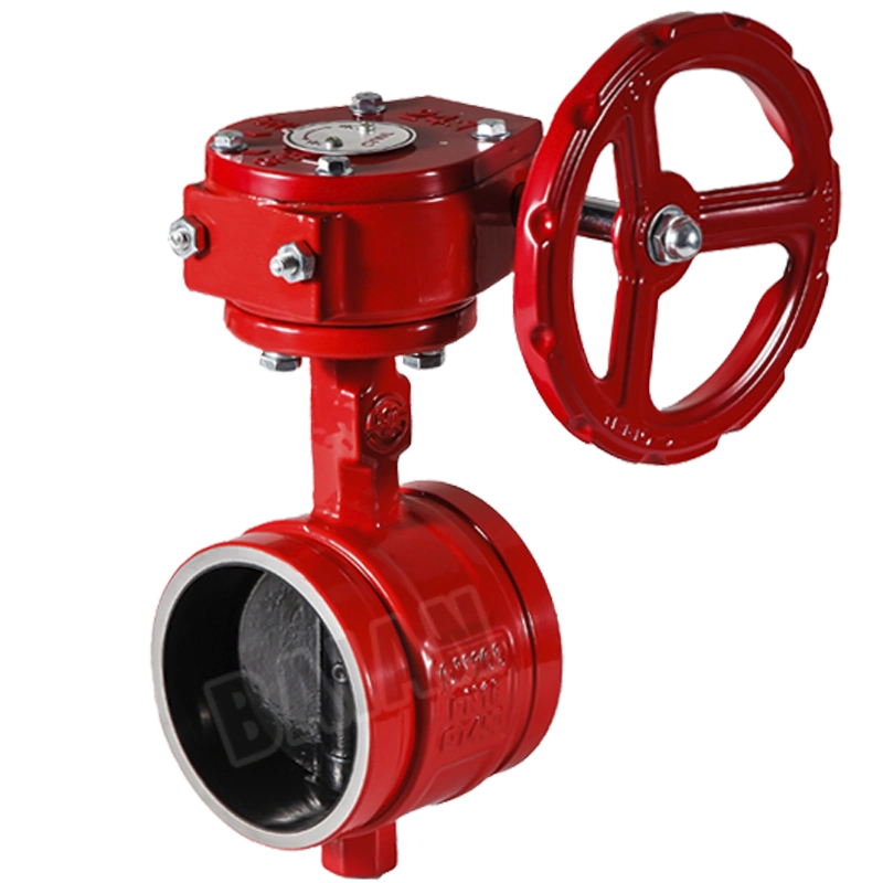
Le vanne papillon, with its rotating disc, is a more modern counterpart. A quarter-turn of its handle can pivot the disc from a position of full obstruction to one of parallel alignment with the flow, offering a quicker, though sometimes less precise, method of control.
Le clapet anti-retour is the system's embodiment of one-way logic. It permits water to flow forward towards a fire but swings shut to prevent it from flowing backward, protecting the municipal water supply from contamination and preventing the system from losing pressure.
Then there are the more complex actors, like the deluge valve. This valve holds back water from an entire network of open-nozzle sprinklers. It remains closed until a separate fire detection system—a smoke or heat detector—senses a fire and sends a signal, causing the valve to trip and flood the entire area. These are used in high-hazard zones like power plants or aircraft hangars, where a rapid, overwhelming response is necessary.
Each of these valves, from a simple check valve to a complex deluge assembly, is a potential point of failure. The purpose of testing is to challenge them, to simulate the demands of a real fire and ask: Will you open? Will you close? Will you hold the pressure? Will you respond to the signal? The answers to these questions, discovered during a peaceful, controlled test, are infinitely more valuable than discovering them amidst the chaos of a real fire.
The Specter of Failure: Common Reasons Valves Falter
A valve's failure is rarely a sudden, spontaneous event. It is more often a slow decay, a story of neglect written in the language of chemistry and time. One of the most common antagonists is corrosion. The constant contact between metal and water, especially if the water has a high mineral or oxygen content, can lead to rust and deterioration. This corrosion can "freeze" a valve in place, making it impossible to operate, or it can eat away at the sealing surfaces, causing persistent leaks that bleed the system of its vital pressure.
A related affliction is tuberculation, a specific form of corrosion where iron bacteria create nodules, or tubercles, on the inside of pipes and valves. These growths act like cholesterol in an artery, restricting flow and dramatically reducing the amount of water that can reach a fire. A system that appears healthy based on static pressure alone might be severely compromised by tuberculation, a fact that only a flow test can reveal.
Human interference is another significant cause of failure. Valves can be improperly closed after a previous maintenance or test and never reopened. This simple oversight is one of the leading causes of sprinkler system failure in real fire events. Sometimes, valves are tampered with, or their supervisory switches, which send a signal to a control panel if the valve is not fully open, are disabled.
Finally, there is the simple wear and tear of aging components. Seals and gaskets can become brittle and crack. Moving parts can seize from a lack of exercise. Like any mechanical device, a fire valve requires periodic operation to remain in good working order. The quarterly or annual test is not just an inspection; it is a necessary exercise to keep the valve's joints limber and its pathways clear.
Navigating the Regulatory Labyrinth: Understanding NFPA 25
In the world of fire protection, standards are not arbitrary rules; they are the collected wisdom of past tragedies. The most widely recognized standard governing the inspection, testing, and maintenance (ITM) of water-based fire protection systems is the National Fire Protection Association's NFPA 25, Standard for the Inspection, Testing, and Maintenance of Water-Based Fire Protection Systems. The 2025 edition of this standard represents the latest consensus on best practices, and its principles are adopted or used as a benchmark by authorities across the globe, from South America to the Middle East.
NFPA 25 provides a minimum schedule and a set of procedures for ITM. It is a performance-based standard, meaning its goal is to ensure the system works as intended. It is not a guide for designing or installing systems, but for ensuring they remain functional throughout their life. For valves, NFPA 25 specifies the frequency and method of testing. For example, it typically requires main control valves to be operated through their full range and returned to their normal position annually (a "full-flow" test is not always required, but a main drain test is). It mandates that pressure gauges be checked for accuracy and that alarms, which signal water flow or valve tampering, are functioning correctly.
For facility managers in Russia, Southeast Asia, or South Africa, adhering to NFPA 25, or the local code that is often based upon it, is the cornerstone of due diligence. It provides a clear, defensible framework for maintaining the system. In the event of a fire, proof of compliance with NFPA 25 can be a powerful defense against claims of negligence, demonstrating that a responsible and systematic effort was made to ensure the system's readiness.
| Valve Type | Primary Function | Common Application | Typical NFPA 25 Test Frequency | Key Test Objective |
|---|---|---|---|---|
| Vanne à guillotine | Isolate system sections | Main control, sectional control | Annually (operated); Quarterly (visual inspect) | Confirms valve can be fully opened/closed; no leaks. |
| Vanne papillon | Isolate system sections | Main control, sectional control | Annually (operated); Quarterly (visual inspect) | Confirms valve can be fully opened/closed; position indicator is accurate. |
| Clapet anti-retour | Prevent backflow | At fire pump discharge, city water connection | 5-Yearly (internal inspection) | Ensures clapper is free-moving and prevents backflow. |
| Deluge Valve | Admit water to dry pipe/nozzles | High-hazard areas (e.g., chemical plants) | Annually (full trip test) | Confirms the valve trips correctly upon a detection signal. |
| Réducteur de pression | Control system pressure | High-rise buildings, standpipe systems | Annually (full flow test) | Verifies correct downstream pressure is maintained under flow conditions. |
Step 1: Pre-Test Preparations and Safety Protocols
Before a single drop of water is intentionally released, a series of preparatory steps must be undertaken. This phase is not preliminary; it is integral to a safe, effective, and non-disruptive test. To neglect these steps is to risk a false alarm, property damage, or even personal injury. It is the professional's equivalent of a surgeon scrubbing in before an operation.
Assembling Your Toolkit: Essential Gear for the Test
A craftsperson is only as good as their tools, and testing a fire valve is a craft. You will need a specific set of equipment, and each item has a purpose.
- Calibrated Pressure Gauges: You will need at least two. One to read the static and residual pressure at the main control valve riser, and another to attach to a hydrant or test header if you are conducting a full flow test. Their calibration is paramount; an inaccurate gauge provides false data, making the entire test meaningless. They should be calibrated annually.
- Pitot Tube and Gauge: If you are measuring flow from a hydrant, a pitot tube is used to measure the velocity pressure of the water stream, which can then be converted to a flow rate in liters or gallons per minute.
- Valve Wrenches: You will need the appropriate wrenches to operate the main drain valve, test connections, and potentially the main control valve itself.
- Safety Cones and Barrier Tape: The water discharged during a test can be substantial and forceful. You must cordon off the area to prevent vehicles or pedestrians from entering the water stream or slipping on wet surfaces.
- Two-Way Radios or Mobile Phones: Communication is key, especially if one person is at the control valve and another is at a remote test location. Clear communication prevents misunderstandings and ensures the test is conducted smoothly.
- Personal Protective Equipment (PPE): This is non-negotiable. At a minimum, this includes safety glasses to protect from spray, sturdy waterproof gloves for grip and protection, and non-slip, waterproof boots. Hearing protection may also be needed near a fire pump.
The Paper Trail: Documentation and Notification
The most critical non-physical tool is communication. Before commencing the test, you must notify all relevant parties.
- The Alarm Monitoring Company: This is the first and most important call. The test will almost certainly trigger a water-flow alarm. If the monitoring company is not notified, they will dispatch the fire department, resulting in a false alarm, a potential fine, and a loss of credibility. You must provide them with the company and building name, the address, your name and contact number, and the estimated duration of the test. Crucially, you must call them back immediately after the test is complete to put the system back online.
- The Fire Department (Non-Emergency Line): In some jurisdictions, it is a requirement or at least a courtesy to inform the local fire department of your planned test. This prevents confusion if they receive a call from a member of the public who sees a large amount of water.
- Building Management and Occupants: If the test might disrupt water supplies or create noise, building management and occupants should be given advance notice. This is a matter of professional courtesy and good customer relations.
- Have Your Logbook Ready: Before you start, have your inspection form or logbook open. You should be prepared to record data in real-time. Trying to remember the readings later is a recipe for inaccuracy.
Personal Protective Equipment (PPE): Your First Line of Defense
Let us pause and consider the physical reality of the test. You will be working with water under high pressure. Pipes can burst, fittings can fail, and water can spray unpredictably. The water itself may be stagnant and dirty. Your PPE is your personal armor.
- Eye Protection: A sudden spray of water, potentially carrying rust or debris, can cause serious eye injury. Safety glasses or goggles are essential.
- Gloves: Operating old, stiff valves requires significant torque. Heavy-duty, waterproof gloves protect your hands from cuts and abrasions while providing a better grip.
- Footwear: The area around the test drain will become a small flood zone. Steel-toed, non-slip, waterproof boots protect you from falling objects, slips, and wet feet, which can become a serious distraction and discomfort.
Putting on your PPE is a mental switch. It signals the transition from planning to execution and puts you in a mindset of safety and professionalism.
Step 2: The Static Pressure Test – Gauging the System's 'Resting Heart Rate'
The first measurement we take is the static pressure. Think of this as the system's resting blood pressure. It is the amount of pressure stored in the pipes when no water is moving. This reading is our baseline, our reference point against which all other measurements will be compared. It tells us the potential energy available to fight a fire.
Locating and Identifying the Correct Valves and Gauges
Your first task is to orient yourself. Using the building's fire system drawings, locate the main control valve assembly for the system you are testing. This is typically found in a dedicated fire riser room, often in the basement or on the ground floor. You are looking for a large-diameter pipe coming into the building, which will have a main control valve (likely a gate or butterfly valve) and a set of pressure gauges. There will be one gauge upstream (before) the main check valve and one downstream (after) it. For our static pressure test, we are interested in the pressure on the system side, which is typically the downstream gauge. You will also need to locate the main drain valve, which is a smaller valve assembly that allows you to discharge water from the system for the flow test.
The Procedure: How to Correctly Read Static Pressure
The procedure is straightforward but requires precision.
- Verify Gauge Accuracy: Before you even read the number, look at the gauge. Does it appear to be in good condition? Is the needle resting at zero when there is no pressure? While you cannot fully test its calibration in the field, a visual inspection can reveal obvious defects.
- Read the Gauge: With the system fully pressurized and no water flowing, read the pressure on the gauge located on the system side of the main control valve. The pressure is typically measured in Pounds per Square Inch (PSI), Bars, or Kilopascals (kPa). Be sure to note the units.
- Record the Reading: Immediately write down this number in your logbook, clearly labeling it "Static Pressure." For example: "Static Pressure: 125 PSI."
Interpreting the Reading: What Does the Number Mean?
This single number is a vital piece of data. What does it tell you?
- Comparison to Design: The static pressure should be consistent with the system's design specifications and the pressure available from the municipal water supply or fire pump. If the design requires 150 PSI and you are only reading 90 PSI, there is a significant problem with the water supply itself.
- Comparison to Previous Tests: The most powerful use of the static pressure reading is trend analysis. Compare this reading to the results from the last several tests (quarterly or annually). A stable reading over time is a sign of a healthy, tight system. A reading that is significantly lower than previous tests is a major red flag. It could indicate a partially closed valve somewhere upstream (perhaps in the street), a major underground leak, or a problem with the city's water supply. A slow, gradual decline in static pressure over many months could indicate a small, developing leak somewhere in the vast network of pipes.
A correct static pressure reading is the foundation upon which the rest of the test is built. Without an accurate baseline, your flow test results will be meaningless.
Step 3: The Flow Test (Residual Pressure) – Simulating a Real-World Fire Event
Now we move from a state of rest to a state of action. The flow test is designed to simulate the system's performance during a fire. By opening a drain and letting a large volume of water flow, we can measure how much the pressure drops. The pressure reading while water is flowing is called the residual pressure. This test reveals the system's true character and its ability to deliver both pressure and volume, which are the two ingredients needed to extinguish a fire.
Understanding Residual Pressure: The System Under Stress
Imagine a garden hose. With the nozzle closed, the pressure inside is static. When you open the nozzle, water flows, and the pressure you feel at the nozzle is residual. The more you open the nozzle, the more water flows, and the lower the residual pressure becomes due to friction loss inside the hose.
The same principle applies to a fire sprinkler system. The residual pressure tells us how much "push" is left in the system to deliver water to the highest and most remote sprinkler head, even while other sprinklers are operating. A system with high static pressure but very low residual pressure is "weak." It has potential, but it cannot deliver on its promise. This condition is often caused by obstructions like tuberculation or a partially closed valve, which act like a clog in the system's arteries.
The Main Drain Test: A System-Wide Health Check
The most common method for performing a flow test is the main drain test. It provides a good overall assessment of the water supply's health up to the main riser.
- Prepare for Discharge: Before you open the drain, ensure your safety zone is secure and direct the discharge hose (if one is used) to a safe location, away from landscaping, walkways, and sensitive equipment. Be aware of potential erosion.
- Initial Pressure Reading: Confirm your static pressure reading one last time before opening the drain.
- Slowly Open the Main Drain: The main drain valve should be opened slowly and completely. Opening it too quickly can cause a pressure surge, and not opening it completely will give you a misleadingly high residual pressure reading.
- Observe the Flow: As the water discharges, observe the stream. It should be powerful and full. A sputtering or weak flow is an immediate sign of a problem, such as trapped air or a blockage.
- Read the Residual Pressure: While the water is flowing steadily, have a second person read the pressure on the same gauge you used for the static pressure. The needle will drop from the static reading and stabilize at a lower number. This is your residual pressure.
- Record the Reading: Immediately record this value in your logbook, labeled "Residual Pressure." For example: "Residual Pressure: 95 PSI."
- Slowly Close the Main Drain: This is one of the most critical steps. Close the drain valve slowly. Closing it abruptly will cause a massive pressure spike known as water hammer, which can be violent enough to break pipes, fittings, and even the valve itself. It should take at least five full turns of the handwheel to close the valve.
- Verify System Recovery: After the drain is closed, watch the pressure gauge. The pressure should return to the original static pressure reading. If it returns to a lower pressure, you may have a new problem.
The Inspector's Test Connection: A Localized Check
In addition to the main drain, sprinkler systems have an inspector's test connection. This is typically a valve located at the most remote point of the system, with an orifice size that simulates the flow of a single sprinkler head. Opening this valve is used primarily to test the water-flow alarm, not to assess the overall health of the water supply. However, it is a part of a comprehensive valve testing program, as it ensures the system's detection and notification functions are working. The procedure is similar: notify the monitoring station, open the valve, confirm the alarm sounds within the time specified by NFPA 25 (usually 60-90 seconds), close the valve, and reset the alarm.
| Test Type | Purpose | Water Volume Discharged | Primary Data Gathered | Typical Frequency (NFPA 25) |
|---|---|---|---|---|
| Main Drain Test | Assess health of water supply (valves, piping) | High | Static & Residual Pressures | Quarterly/Annually |
| Inspector's Test | Test water-flow alarm functionality | Low (simulates one sprinkler) | Alarm activation time | Quarterly/Annually |
| Full Flow Test | Verify performance of fire pump or hydrant supply | Very High | Flow (LPM/GPM) & Residual Pressure | Annually (for pumps); 5-Yearly (for systems) |
Step 4: Analyzing the Results – From Numbers to Actionable Insights
You have now collected two critical numbers: static pressure and residual pressure. These are not just entries in a logbook; they are diagnostic clues. The art of the professional is to interpret these clues to understand the condition of the system.
The Critical Comparison: Static vs. Residual Pressure
The most important analysis is the comparison between the two readings. We are interested in the percentage drop in pressure. The formula is:
Percentage Drop = ((Static Pressure – Residual Pressure) / Static Pressure) * 100
Let's consider two scenarios:
-
Scenario A: Static = 125 PSI, Residual = 115 PSI.
- Drop = 10 PSI.
- Percentage Drop = (10 / 125) * 100 = 8%.
- Interpretation: This is a very healthy result. A drop of less than 10-15% on a main drain test indicates a strong, unobstructed water supply. The system has plenty of pressure rezerv to perform its job.
-
Scenario B: Static = 125 PSI, Residual = 75 PSI.
- Drop = 50 PSI.
- Percentage Drop = (50 / 125) * 100 = 40%.
- Interpretation: This is a major red flag. A large percentage drop signifies a high degree of friction loss. The "arteries" of the system are "clogged." This could be a partially closed valve that you were unaware of, or severe internal pipe corrosion (tuberculation). While the resting pressure is good, the system cannot maintain that pressure under flow. It is weak and may not be able to supply adequate water to a fire.
Trend Analysis: Looking at Data Over Time
A single test gives you a snapshot. A series of tests over several years gives you a movie. By plotting your static and residual pressures over time, you can detect gradual degradation. For example, if your main drain test result was an 8% drop five years ago, a 10% drop three years ago, and is a 15% drop today, this trend suggests a slowly worsening problem, likely the buildup of corrosion or sediment in the pipes. This proactive analysis allows you to schedule investigative work and pipe flushing before the system fails a test or, worse, fails in a fire.
When to Raise the Red Flag: Identifying Failing Results
While a significant percentage drop is a primary indicator, the ultimate pass/fail criterion is whether the system can still deliver the required flow and pressure as specified in its original hydraulic design calculations. If the residual pressure during a flow test drops below the minimum required for the most demanding sprinkler head, the system is inadequate. Any test that reveals a closed or partially closed valve that was supposed to be open is an immediate failure and must be corrected. Any failure to operate a valve, or any leak that cannot be stopped, constitutes a failed test. In such cases, the valve must be repaired or replaced by a qualified contractor, and the system must be re-tested.
Step 5: Testing Specific Valve Types – A Deeper Dive
While the main drain test assesses the overall supply, individual valves have their own testing requirements to ensure they perform their specific roles. This requires a more nuanced approach.
Gate Valves and Butterfly Valves: The On/Off Switches
These are the most common control valves. The primary test is simply to ensure they can be operated. Annually, each control valve should be operated through its full range of motion, from fully open to fully closed, and then back to fully open.
- The Procedure: During this test, you are feeling for smooth operation. Is the valve excessively difficult to turn? Does it make grinding noises? Does it get stuck? These are signs of internal corrosion or damage. After returning the valve to the open position, you must verify it is fully open. For an OS&Y (Outside Stem and Yoke) gate valve, the stem should be fully raised. For a butterfly valve, the indicator should show "OPEN" and be aligned with the pipe.
- Supervisory Switches: Most control valves are supervised. This means they have an electronic switch that sends a trouble signal to the fire alarm panel if the valve is even slightly closed. Part of the test is to close the valve just one or two turns and confirm that the trouble signal is received at the control panel. This verifies the alarm system is watching the valve as it should. Ensuring you have high-quality, certified valves from a trusted fire fighting valve manufacturer is the first step in ensuring these tests are passed consistently (cnbaianfire.com, n.d.).
Check Valves: The System's One-Way Streets
Check valves are tested to ensure they are holding pressure and preventing backflow. A simple test involves observing the system-side pressure gauge after a main drain test. If the pressure holds steady, the check valve is likely doing its job. A more thorough test, required by NFPA 25 every five years, involves an internal inspection. This requires de-pressurizing the system and opening the valve's cover plate to visually inspect the clapper, hinge, and seat for damage, debris, or restricted movement.
Deluge and Pre-Action Valves: The Sentinels of High-Hazard Areas
These valves require a "trip test," which is more involved. A pre-action system, which has air in the pipes and closed sprinklers, is designed for areas like data centers where accidental water damage is a major concern. A deluge system has open sprinklers and is for high-hazard areas.
- The Trip Test: The test involves activating the detection system (e.g., using a heat gun on a heat detector or canned smoke on a smoke detector). This should send a signal that trips the deluge or pre-action valve, allowing water to flow. For a pre-action system, you would then open the inspector's test valve to simulate a sprinkler opening. The test measures the time from detector activation to water delivery at the most remote point. This time must be within the limits set by the relevant standard. These tests are complex and are almost always performed by specialist fire protection contractors.
Pressure Reducing and Relief Valves: The System's Regulators
These valves are common in high-rise buildings and on fire pump installations. A pressure reducing valve (PRV) is tested by establishing a flow through the valve and measuring the downstream pressure to ensure it is being correctly regulated to the design specification. A pressure relief valve, which is designed to open and relieve excess pressure, is tested by slowly increasing the system pressure (using the fire pump) to the point where the valve is set to open, and confirming that it does so at the correct pressure.
Step 6: Post-Test Procedures – Restoring the System to Service
The test is not complete until the system is fully restored to its normal, ready state. This phase is as important as the test itself. A mistake here can leave the building unprotected.
The Systematic Shutdown: Closing Drains and Vents
As emphasized earlier, the main drain valve must be closed slowly. This gradual closure, taking at least 30-60 seconds, allows the column of moving water to slow down gently, preventing the violent shockwave of a water hammer. Once the drain is fully closed, double-check that any other test valves or vents that were opened are also closed.
Re-Pressurizing the System: A Gentle Approach
If the main control valve was closed for the test, it must be reopened with equal care. Open the valve slowly, just a crack at first. You should hear the sound of water beginning to refill the system. Opening the valve too quickly can cause a pressure surge that can damage fittings or even break sprinklers. Once the pressure on the upstream and downstream gauges has equalized, you can open the valve fully.
Verifying System Readiness: Final Checks
This is your final walkthrough.
- Valves: Physically check every valve that was operated. Ensure they are in their normal position (usually open). If they are supposed to be locked or chained, re-secure them. If they are supervised, check the fire alarm panel to ensure all "trouble" signals have cleared.
- Gauges: The system pressure should have returned to the original static pressure.
- Alarms: Reset the fire alarm panel. 4s. Notification: This is the crucial final call. Contact the alarm monitoring company and inform them that the testing is complete and the system is back in normal service. They will confirm that they are once again monitoring your system for fire signals. Notify building management as well.
The Aftermath: Cleaning Up the Test Site
A professional leaves the site cleaner than they found it. Mop up any significant puddles in the riser room. If the water discharge caused any erosion or mess outside, clean it up. Return all tools to your kit.
Step 7: Documentation and Record-Keeping – The Foundation of Compliance
If a test is not documented, it did not happen. Meticulous record-keeping is the final, and perhaps most enduring, part of the process. These records are your proof of due diligence, your history book for the system, and your guide for future maintenance.
The Anatomy of a Proper Test Report
A proper test tag should be affixed to the valve riser, and a detailed report should be filed. The report must include:
- Date and time of the test.
- Name and qualification of the person performing the test.
- Identification of the specific system and valves tested.
- The static pressure reading.
- The residual pressure reading.
- Any alarm devices tested and the results.
- A description of any deficiencies found (e.g., "Main control valve difficult to operate," "15% pressure drop noted").
- A description of any corrective actions taken ("Valve lubricated," "Recommend internal investigation of piping").
The Role of Records in Audits and Insurance Reviews
These records are not just for you. They will be reviewed by the local fire marshal, the building's insurance provider, and potentially by accrediting bodies. Well-maintained, detailed records demonstrate professionalism and a commitment to safety. They can lead to lower insurance premiums and will be invaluable in the unfortunate event of a fire, as they prove the system was maintained in accordance with established standards. The journey through the mechanics and morals of valve testing brings us to a final reflection.
Advanced Diagnostics and Regional Considerations
The seven-step process forms the backbone of standard fire valve testing. However, the world of fire protection is rich with advanced techniques and specific local challenges, particularly for professionals working across diverse regions like South America, Russia, Southeast Asia, and the Middle East. Understanding these nuances separates a technician from a true fire protection expert.
Beyond the Gauge: Advanced Diagnostic Tools
While pressure gauges are the classic tools, modern technology offers more sophisticated ways to "see" inside the system. Ultrasonic flow meters are a powerful example. These devices can be clamped onto the outside of a pipe and use sound waves to measure the velocity of the water flowing inside, providing a highly accurate flow rate (GPM or LPM) without the need to discharge water through a pitot tube. This is invaluable for conducting fire pump tests or for systems where large water discharges are problematic. It allows for a precise comparison of the system's actual performance against its original hydraulic design calculations.
When a significant, unexplained pressure drop is found, the investigation begins. This is where a methodical approach is key. The first step is always to conduct a "valve run"—physically checking every single control valve on the supply line, including the one in the underground pit in the street, to ensure they are fully open. If all valves are open, the next suspect is a major blockage. This could be a foreign object left in the pipe during a previous repair, or a failed check valve clapper that has broken loose and lodged downstream. Specialized contractors can use camera-equipped robotic crawlers to internally inspect long pipe runs to find such obstructions.
The Challenge of Climate and Water Quality
The procedures outlined by NFPA are universal, but their application must be adapted to local conditions.
- In Russia or other cold climates, testing in winter presents the obvious hazard of ice. Water discharged from a main drain can instantly freeze on walkways and roads, creating a serious slip hazard. Tests must be carefully planned, with salt or sand ready to be applied. Furthermore, for dry-pipe systems, ensuring the low-point drains are completely free of water is critical to prevent a frozen, cracked pipe that could cripple the system.
- In hot, humid climates like Southeast Asia, the primary enemy is accelerated corrosion. The combination of warmth and moisture can speed up the chemical reactions that cause rust. Microbiologically Influenced Corrosion (MIC) is also a greater concern in these environments. This means that trend analysis of flow test results is even more important, as a gradual decline in performance can be a tell-tale sign of aggressive internal corrosion that needs to be addressed.
- In the Middle East, water scarcity and quality are major factors. The water used in fire systems may be desalinated or have a high mineral content, which can lead to scaling and deposits inside valves and pipes, similar to tuberculation. In such regions, the five-year internal inspection acessórios of check valves and strainers is not just a recommendation but a critical task.
The Interplay with Other Fire Equipment
It is a mistake to think of a fire valve in isolation. Its performance directly impacts all the other equipment downstream. The pressure and flow available at a standpipe connection directly determine the effectiveness of a tuyau d'incendie operated by firefighters. A weak supply压力 caused by a partially closed valve means the hose stream will be weak, unable to reach the seat of the fire. Similarly, large, fixed moniteurs d'incendie in industrial facilities require immense volumes of water to be effective. The valves that supply them must be capable of opening fully and providing an unobstructed path. For complex systèmes de mousse, proper valve operation is even more critical, as the system relies on water flow through a proportioner to correctly mix foam concentrate. Insufficient flow can lead to an incorrect foam mixture, rendering the expensive foam agent useless. Therefore, when you test a fire valve, you are also implicitly testing the potential performance of every hose, monitor, and proportioner that depends on it.
Foire aux questions (FAQ)
How often should I test my fire valves?
The frequency depends on the valve type and local regulations, but a general guideline based on NFPA 25 is: control valves (gate, butterfly) are visually inspected quarterly and fully operated annually. Main drain flow tests are typically performed quarterly or annually. Alarms are tested quarterly. More complex valves like deluge and pressure-reducing valves have annual testing requirements.
Can I perform a fire valve test myself?
While a knowledgeable building engineer can perform basic tests like a main drain test, many jurisdictions require that ITM of fire protection systems be carried out by licensed and certified professionals. Complex tests, like a full fire pump flow test or a deluge valve trip test, should always be handled by a qualified fire protection contractor.
What is the difference between a main drain test and an inspector's test?
A main drain test involves opening a large drain at the system riser to flow a high volume of water. Its primary purpose is to test the condition of the water supply by measuring the drop from static to residual pressure. An inspector's test involves opening a small valve at a remote point in the system, which simulates the flow of a single sprinkler. Its primary purpose is to verify that the water-flow alarm activates correctly.
What is water hammer and how can I prevent it during testing?
Water hammer (or hydraulic shock) is a powerful pressure surge created when a fluid in motion is forced to stop or change direction suddenly. In fire valve testing, it is most commonly caused by closing a drain valve too quickly. The moving column of water slams to a halt, creating a shockwave that can break pipes, fittings, and gauges. To prevent it, always close all valves slowly and smoothly.
My static pressure reading is much lower than the last test. What's the first thing I should check?
A significant drop in static pressure is a serious issue. The first thing to check is that all upstream control valves are fully open. This may involve checking a valve in an underground pit (a PIV or post indicator valve) or notifying the municipal water department to ensure there are no issues or closed valves on their end. A major underground leak is another possibility.
What happens if a valve fails the test?
If a valve is found to be inoperable, leaking, or causing a failed flow test, it must be immediately reported and scheduled for repair or replacement. The system should be tagged as impaired, and the building owner, insurance company, and local fire authority must be notified according to local procedures.
A Final Reflection on Responsibility
The methodical process of testing a fire valve, from the initial notifications to the final signature in a logbook, is more than a sequence of technical tasks. It is a dialogue with the building's hidden infrastructure. It is an act of foresight, a commitment to a future moment of crisis that we hope never comes. Each turn of a valve, each reading of a gauge, is a question we ask of the system: "Are you ready?" The numbers and the flow of water provide the answer. For the professional entrusted with this duty, the goal is to ensure that the answer is always, unequivocally, "Yes." This is the essence of fire protection and the core of our shared responsibility to safeguard lives and property.
Références
chinesestandard.net. (2023). GB 4351-2023: Portable fire extinguishers. Chinese Standard. https://www.chinesestandard.net/PDF.aspx/GB4351-2023
cnbaianfire.com. (n.d.). Fire fighting valve. Bai'an Fire. https://www.cnbaianfire.com/category/fire-fighting-valve/
cnbaianfire.com. (n.d.). Foam system. Bai'an Fire.
KSB. (2025). Sprinkler pumps, valves and all-in solutions for fire protection systems. KSB.
National Fire Protection Association. (2022). NFPA 25: Standard for the inspection, testing, and maintenance of water-based fire protection systems. NFPA.
Rosenbauer. (n.d.). Automatic fire extinguishing & suppression systems. Rosenbauer.
Rosenbauer. (n.d.). Fire fighting hose nozzles & monitors. Rosenbauer.
Wilo. (2025). Firefighting. Wilo.