
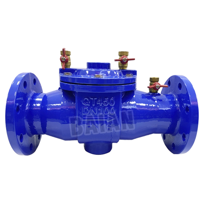
DF41X-16Q Back Flow Preventer Parts
The DF41X-16Q Back Flow Preventer Parts is a hydraulic device preventing backflow pollution with double check valves and air gaps. Meeting CJ/T160-2002, it suits horizontal installation in water systems, ensuring ≤16 bar pressure and 0°C-80°C safety.
See more at Back Flow Preventer Catalog!
DF41X-16Q Back flow Preventer Parts
SPECIFICATIONS
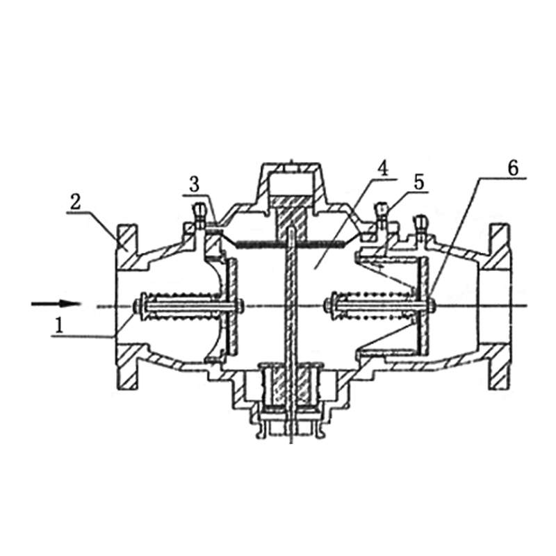
1.The back flow preventer is a hydraulic control combination device that strictly limits the flow of water in the pipeline to one direction, developed based on the serious back flow pollution of tap water supply equipment, especially drinking water pipelines, and the lack of effective back flow pollution prevention devices.
2.Its function is to prevent the medium in the pipeline from flowing back under any working conditions, so as to achieve the purpose of avoiding back flow pollution.
3.At present, the back flow preventer is mainly divided into two categories: low-resistance back flow preventer and pressure-reducing back flow preventer.
4.According to national standards, the head loss of low-resistance back flow preventer is less than 3 meters, and the head loss of pressure-reducing back flow preventer is less than 7 meters.
FEATURE :
1.The product has a unique design, beautiful appearance, simple installation and convenient maintenance.
2.Double check valve plus air partition completely prevents back flow pollution under any working conditions.
3.Accurate calculation, excellent processing, reliable performance and sensitive action.
4.Designed according to CJ/T160-2002 standard.
5.Environmentally friendly coating is sprayed on the inner and outer surfaces to ensure the corrosion resistance and safety of the product. 6. If the back flow preventer needs to be used in seawater, please indicate it when ordering.
Installation requirements
1.The back flow preventer should be installed horizontally, and the installation environment should be clean and have sufficient maintenance space.
2.A control valve, filter and flexible joint should be installed before the valve, and a control valve should be installed after the valve for maintenance.
Installation location:
1.Behind the water meter where the tap water network is connected to the user's household pipe.
2.Installed at the beginning of the pipe that connects the non-domestic drinking water and sewage pipes to the domestic water pipe.
3.On the water inlet pipe of the domestic drinking water tank (when the water tank is filled with water from the bottom).
4.Installed on the pump suction pipe when a booster pump is connected in series on the domestic drinking water pipe.
5.The installation site should keep the environment clean and sanitary, and disinfect the environment when necessary.
Installation and commissioning
1.Before formal installation, all pipes should be thoroughly flushed.
2.The back flow preventer should be installed in a horizontal position, which should be convenient for commissioning and maintenance, and can detect water leakage or faults in time. After installation, the valve body of the back flow preventer should not bear the weight of the pipeline, and pay attention to avoid freezing and man-made damage.
3.Maintenance gate valves should be installed at both ends of the back flow preventer, filters should be installed before the inlet, and at least one end should be equipped with a flexible joint. However, for pipelines that are only used in emergency situations (such as fire protection system pipelines), the possibility of water supply interruption in emergency situations caused by impurities blocking the filter mesh should be considered.
WORKING PRESSURE
Maximum working pressure 16 bar (230psi).
STANDARD
Product testing is carried out in accordance with cj/t60-2002 Industrial valve pressure test.
TEMPERATURE RANGE
0 °C to 80°C.
COATING
Fusion Bonded Epoxy Coating.
Leave Your Message